


Pilot-RC reserves the right to update the model, instructions and limited warranty without notice.
If you have any problems and questions, please contact Pilot-RC:
Web: www.Pilot-Rc.com
Email: [email protected], [email protected]
Phone: +86 760 88781293 FAX: +86 760 88780293
Address: No34, Chengnan Er Road, Zhongshan City, 528455, Guangdong, Province, China.
3- Assembly
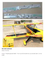
Please note that pictures are for reference only. Some pictures shown are from other models which
follow the same build steps.
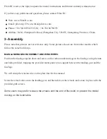
MAIN LANDING GEAR ASSEMBLY AND WING WIRES:
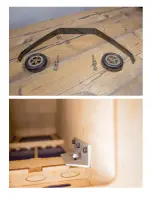
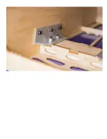
Position the fuselage upside down and screw on the carbon undercarriage to the fuselage using the nuts
and bolts provided, trapping the provided metal guide wires support between the landing gear and the
fuselage.
We will crimp the tension wires to the plate later in this manual.
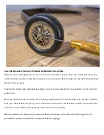
Screw the wheel axles on to the landing gear, and then slide on the wheels and secure in place with the
provided grub screws.
Some users may prefer to leave the wheels until the end of the build, to prevent the model
moving on the build table.
Summary of Contents for Pitts Challenger
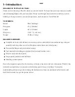
Page 1: ...Pitts Challenger 87 2 20m 100cc MANUAL...
Page 7: ......
Page 8: ......
Page 9: ......
Page 10: ......
Page 11: ......
Page 13: ......
Page 14: ......
Page 15: ......
Page 17: ......
Page 18: ......
Page 19: ......
Page 21: ......
Page 22: ......
Page 23: ......
Page 24: ......
Page 25: ......
Page 26: ......
Page 28: ......
Page 29: ......
Page 30: ......
Page 32: ...the pushrods provided...
Page 33: ......
Page 34: ......
Page 35: ......
Page 37: ......
Page 38: ......
Page 39: ......
Page 40: ......
Page 41: ......
Page 43: ......
Page 44: ......
Page 45: ......
Page 47: ......
Page 48: ......
Page 49: ......
Page 50: ......
Page 51: ......
Page 52: ......
Page 54: ......
Page 55: ......
Page 56: ......
Page 58: ......
Page 60: ......
Page 61: ...Note that the two laser cut holes are for the fuel and smoke tank vents...
Page 63: ......
Page 64: ......
Page 66: ......
Page 67: ......
Page 68: ......
Page 69: ......
Page 71: ......
Page 72: ......
Page 74: ......
Page 75: ......
Page 76: ......
Page 78: ......
Page 80: ......
Page 82: ......
Page 83: ......