
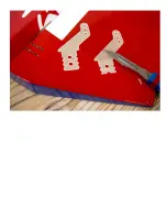


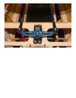


AILERON SERVO INSTALLATION:
Locate and cut the covering where the servo will be installed. We recommend cutting only the diameter
of the main part of the servo. Allow the servo to sit on top of some Oracover, thus trapping and
securing the Oracover in place.
Use the included string and tabs to route the servo wire through the wing and screw the servo in place
having added any extension leads as necessary.
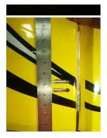
For the top wing servos, each aileron will require two separate extension leads. The first extension lead
should run inside the lower wing, to the location of the outer wing strut. The second extension lead
should be run inside the wing strut itself. In this way, upon setup of the model at the field, you will
mount the lower wing first, then connect the strut and its extension lead, and then connect the top wing
to the strut and its extension. This will allow the removal of both the wings and the struts for easy
transportation.
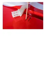
Centre the servo with your transmitter, attach the servo arm and connect the servo to the ailerons with
Summary of Contents for Pitts Challenger
Page 1: ...Pitts Challenger 87 2 20m 100cc MANUAL...
Page 7: ......
Page 8: ......
Page 9: ......
Page 10: ......
Page 11: ......
Page 13: ......
Page 14: ......
Page 15: ......
Page 17: ......
Page 18: ......
Page 19: ......
Page 21: ......
Page 22: ......
Page 23: ......
Page 24: ......
Page 25: ......
Page 26: ......
Page 28: ......
Page 29: ......
Page 30: ......
Page 32: ...the pushrods provided...
Page 33: ......
Page 34: ......
Page 35: ......
Page 37: ......
Page 38: ......
Page 39: ......
Page 40: ......
Page 41: ......
Page 43: ......
Page 44: ......
Page 45: ......
Page 47: ......
Page 48: ......
Page 49: ......
Page 50: ......
Page 51: ......
Page 52: ......
Page 54: ......
Page 55: ......
Page 56: ......
Page 58: ......
Page 60: ......
Page 61: ...Note that the two laser cut holes are for the fuel and smoke tank vents...
Page 63: ......
Page 64: ......
Page 66: ......
Page 67: ......
Page 68: ......
Page 69: ......
Page 71: ......
Page 72: ......
Page 74: ......
Page 75: ......
Page 76: ......
Page 78: ......
Page 80: ......
Page 82: ......
Page 83: ......