


Installation :
Step 1:
Wall or shelf mount the unit. Rubber feet and screws are supplied in the accessory kit.
Step 2:
Verify the power switch on the right side of the unit is set to OFF. Attach the included power pack to a
wall or power strip receptacle, then attach the other end to the jack on the right side of the unit labeled 12VDC.
Step 3
: Make sure any amplifiers (if using any) are turned OFF prior to any connections.
Step 4:
Connect a RCA cable (supplied in the accessory kit) to the CHANNEL A (OUT) jack on the left side of
the unit. Connect the other end of the RCA cable to a phones MOH port, PA amplifier or speaker. For dual output
applications follow the same procedure for the CHANNEL B (OUT).
Step 5
: (Optional) For messaging only applications the existing BGM (Background Music) can be fed through
the iLink. Connect the audio source to the CHANNEL A or B (IN) jack(s) on the left side of the unit. This jack
must only be fed signal level audio - ANY AMPLIFIED AUDIO WILL DAMAGE THE UNIT.
Step 6:
Connect an Ethernet cable (supplied in the accessory kit) to the LAN jack on the right side of the unit.
Connect the other end to a 10/100 speed switch or hub. If unit is being used in WiFi mode attach antenna to
antenna jack marked ANT
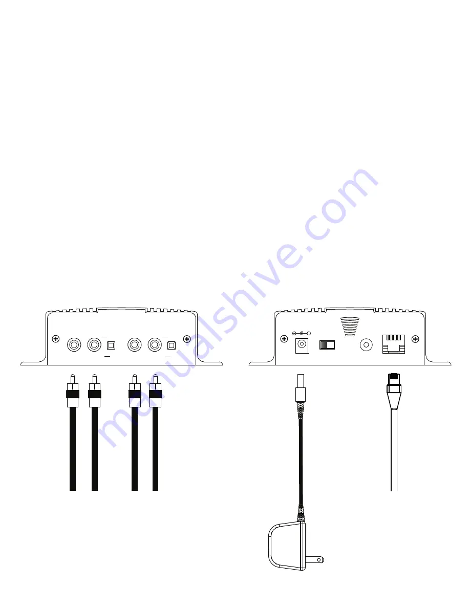
Wiring Diagram
Left Side Right Side
To Switch or Hub
To MOH or P
A
From BGM Source
(Optional)
To MOH or P
A
(Optional)
CHANNEL A
CHANNEL B
IN
OUT
IN
OUT
600Ω
▄
█
MADE IN USA
8Ω
▄
8Ω
600Ω
█
From BGM Source
(Optional)
10
12VDC
500mA
+
POWER
ON
(1)
OFF
(0)
LAN
MIC
ANT
Summary of Contents for iLink LCD
Page 1: ...iLink LCD iLink LCD Wireless Installation User Manual...
Page 2: ......


