


VACUUM CONVEYORS
4
SAFETY INSTRUCTION
Instructions for building into a system
PIAB vacuum conveyors are CE marked. The person
who installs the conveyor in another main system has
the responsibility of carrying out a risk analysis when
this is desired.
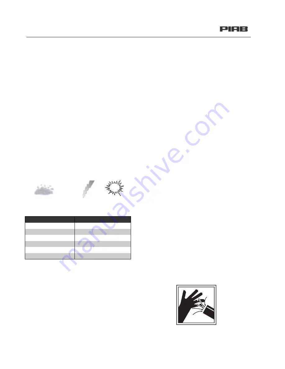
Dust explosions
When handling and conveying dry powders and mate-
rial consisting of small particles, there is a risk that a
dust explosion may occur. A dust explosion may occur
when certain finely divided materials are mixed with air
(oxygen) and then are ignited by, for example, a spark.
In order to minimise the risk of dust explosions, all in-
cluded parts of the conveying system must be connect-
ed to one and the same point of earth (equipotential)
according to applicable regulations. It is also important
not to smoke, weld or carry out other work where the
risk of generation of sparks may be present in the vi-
cinity of the conveyor.
In the table below are some examples of materials that
may cause dust explosions.
The conveyor may not be used in explosive surround-
ings containing the following gases: acetylene, carbon
disulphide, hydrogen, hydrogen sulphide and ethylene
oxide.
ATEX-Atmosphere Explosible and CE.
PIAB vacuum conveyors are not EX classified.
PIAB vacuum conveyors conforms to EU directive 94/
9/EC.
Cleaning of filters
It is important to check and clean/change filters at reg-
ular intervals so that they are not clogged, as this
might lead to the fact that the filters will be subjected
to overload, and that undesired matters or particles
leak from the conveyor.
Emergency stop
The system builder shall provide the machine with an
emergency stop function. As an option to the vacuum
conveyor there is a remote control box with a built-in
emergency stop function.
Start/stop of the conveyor
The conveyor is started either with the provided control
unit or via another main control system. The conveyor
stops if the supply of compressed air is suddenly inter-
rupted. The conveyor must be re-started by the opera-
tor even if the supply of compressed air is reactivated.
Vacuum power at the inlet
Careless usage and incorrect installation of the feed-
ing point of the vacuum system may cause injuries.
The vacuum level is concentrated at the feeding point
and may cause injuries to eyes and mucous mem-
branes.
X
Never aim a suction tube, a feed nozzle or a hose
at anyone.
X
The larger the suction inlet, the higher the power
and danger.
X
The installation must be made so that the inlet
cannot contact the operator and other people.
X
Always remember to disconnect the supply of
compressed air when cleaning or servicing the
vacuum conveyor.
X
Aluminium
Carbon
Aspirin
Magnesium
Cotton
Flour
Iron
Nylon
Cacao
Sugar
Coffee
Corn
Cork
Wood
+
O
2
+
=
Summary of Contents for C 1200 Series
Page 1: ...VACUUM CONVEYING C Series Conveyor Troubleshooting Guide www piab com ...
Page 7: ...VACUUM CONVEYORS 7 CONNECTION EXAMPLES CONTROL UNIT CU 1A B ART NO 01 04 550 ART NO 01 04 552 ...
Page 8: ...VACUUM CONVEYORS 8 CONTROL UNIT CU 1A B WITH FLUIDISATION ART NO 01 04 550 ART NO 01 04 552 ...
Page 10: ...VACUUM CONVEYORS 10 CONTROL UNIT CU 1A B USDA ART NO 01 04 550 ART NO 01 04 552 ...
Page 11: ...VACUUM CONVEYORS 11 CONTROL UNIT CU 2A B ART NO 01 04 540 ART NO 01 04 548 ...
Page 13: ...VACUUM CONVEYORS 13 CONTROL UNIT CU 2A B WITH FLUIDISATION ART NO 01 04 540 ART NO 01 04 548 ...
Page 14: ...VACUUM CONVEYORS 14 CONNECTION EXAMPLES ...
Page 15: ...VACUUM CONVEYORS 15 VALVE UNIT VCC EP VALVE UNIT VCC EP WITH FLUIDISATION ...
Page 18: ...VACUUM CONVEYORS 18 FILTER REPALCEMENT 1 2 3 4 5 ...
Page 19: ...VACUUM CONVEYORS 19 6 7 8 9 10 11 12 ...
Page 29: ...VACUUM CONVEYORS 29 INSIDE COMPONENTS OF MLL PUMPS ...
Page 31: ...VACUUM CONVEYORS 31 L100 CLASSIC COMPONENTS ...
Page 38: ...VACUUM CONVEYORS 38 CONTROL UNIT CU 1B BOTTOM VALVE NC ART NO 01 04 552 ...
Page 39: ...VACUUM CONVEYORS 39 PNEUMATIC DIAGRAM CONTROL UNIT CU 1A BOTTOM VALVE NO ART NO 01 04 550 ...
Page 40: ...VACUUM CONVEYORS 40 CONTROL UNIT CU 1B BOTTOM VALVE NC ART NO 01 04 552 ...
Page 41: ...VACUUM CONVEYORS 41 CONTROL UNIT CU 2B BOTTOM VALVE NC ART NO 01 04 548 ...
Page 44: ...VACUUM CONVEYORS 44 PNEUMATIC DIAGRAM COMPONENT LAYOUT ...
Page 45: ...VACUUM CONVEYORS 45 TIME SIGNAL DIAGRAM MOUNTING ...
Page 50: ...VACUUM CONVEYORS 50 VALVE CONNECTIONS FOR THE VCC EP ...
Page 53: ...VACUUM CONVEYORS 53 PNEUMATIC INJECTION VALVE ...
Page 57: ...VACUUM CONVEYORS 57 NOTES ...
Page 58: ...VACUUM CONVEYORS 58 NOTES ...
Page 59: ...VACUUM CONVEYORS 59 NOTES ...


