


VACUUM CONVEYORS
21
HERDING SINTERED RINSE OFF CLEANING
HERDING SINTERED AIR JET CLEANING
Rinse-off cleaning procedure:
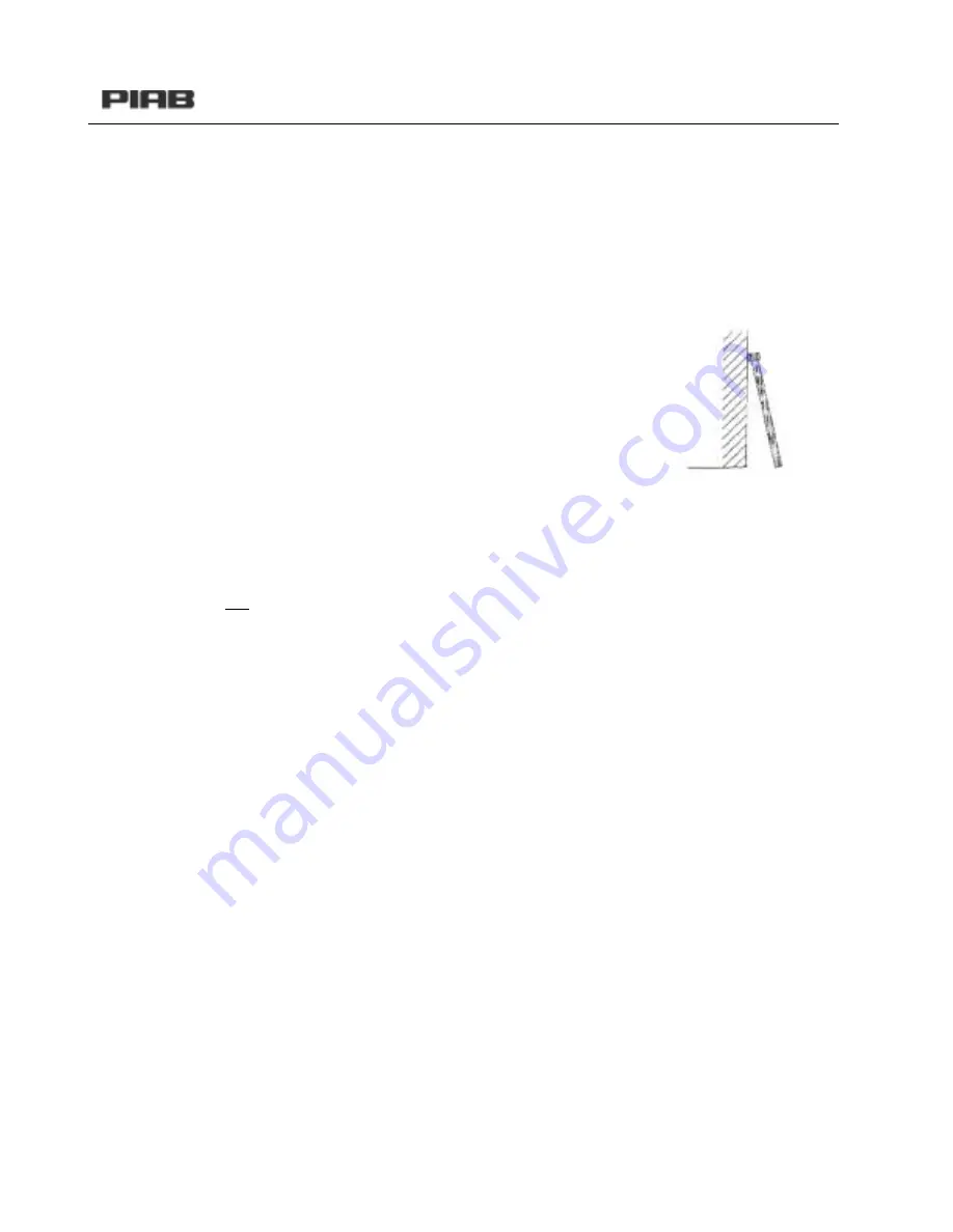
1. Your filter elements have to be dismantled in order to be cleaned.
2. Stand the filter elements in a vertical a position as possible
(e.g. lean them against a wall, see the drawing).
3. No dust should be allowed to get into
the filter elements during the cleaning
operation. It is recommended,
therefore, to cover up the inside of the
filter (e.g. with adhesive tape).
4. Rinse off the dust with gentle water pressure
-Maximum pressure of thewater jet upon impact: 1 bar (14.5 psi)
-Maximum water temperature: 40°C (104F)
5. Turn the filter elements and proceed in like manner for
the rear and the narrow sides.
6. Clean the head and foot zone last, taking care not to
allow any water to get into the filter elements.
7. Leave the filter elements standing at the same acute
angle to dry. Drying must take place at room temperature
(minimum 24 hours).
8. Reinstall the d
dry filter elements in the filter unit.
Air-jet cleaning procedure:
1. Your filter elements have to be dismantled in order to be cleaned.
2. Stand the filter elements in a vertical a position as possible
(e.g. lean them against a wall, see drawing above).
3. No dust should be allowed to get into the filter elements during the cleaning operation.
It is recommended, therefore, to cover up the inside of the filter (e.g. with adhesive tape).
4. Clean off the dust with a gentle air jet
-Maximum pressure of the air jet upon impact: 1 bar (14.5 psi)
5. Turn the filter elements and proceed in like manner for the rear and the narrow sides.
6. Clean the head and foot zone last, taking care not to allow any dust to get into the filter
elements.
8. Reinstall the filter elements in the filter unit.
Summary of Contents for C 1200 Series
Page 1: ...VACUUM CONVEYING C Series Conveyor Troubleshooting Guide www piab com ...
Page 7: ...VACUUM CONVEYORS 7 CONNECTION EXAMPLES CONTROL UNIT CU 1A B ART NO 01 04 550 ART NO 01 04 552 ...
Page 8: ...VACUUM CONVEYORS 8 CONTROL UNIT CU 1A B WITH FLUIDISATION ART NO 01 04 550 ART NO 01 04 552 ...
Page 10: ...VACUUM CONVEYORS 10 CONTROL UNIT CU 1A B USDA ART NO 01 04 550 ART NO 01 04 552 ...
Page 11: ...VACUUM CONVEYORS 11 CONTROL UNIT CU 2A B ART NO 01 04 540 ART NO 01 04 548 ...
Page 13: ...VACUUM CONVEYORS 13 CONTROL UNIT CU 2A B WITH FLUIDISATION ART NO 01 04 540 ART NO 01 04 548 ...
Page 14: ...VACUUM CONVEYORS 14 CONNECTION EXAMPLES ...
Page 15: ...VACUUM CONVEYORS 15 VALVE UNIT VCC EP VALVE UNIT VCC EP WITH FLUIDISATION ...
Page 18: ...VACUUM CONVEYORS 18 FILTER REPALCEMENT 1 2 3 4 5 ...
Page 19: ...VACUUM CONVEYORS 19 6 7 8 9 10 11 12 ...
Page 29: ...VACUUM CONVEYORS 29 INSIDE COMPONENTS OF MLL PUMPS ...
Page 31: ...VACUUM CONVEYORS 31 L100 CLASSIC COMPONENTS ...
Page 38: ...VACUUM CONVEYORS 38 CONTROL UNIT CU 1B BOTTOM VALVE NC ART NO 01 04 552 ...
Page 39: ...VACUUM CONVEYORS 39 PNEUMATIC DIAGRAM CONTROL UNIT CU 1A BOTTOM VALVE NO ART NO 01 04 550 ...
Page 40: ...VACUUM CONVEYORS 40 CONTROL UNIT CU 1B BOTTOM VALVE NC ART NO 01 04 552 ...
Page 41: ...VACUUM CONVEYORS 41 CONTROL UNIT CU 2B BOTTOM VALVE NC ART NO 01 04 548 ...
Page 44: ...VACUUM CONVEYORS 44 PNEUMATIC DIAGRAM COMPONENT LAYOUT ...
Page 45: ...VACUUM CONVEYORS 45 TIME SIGNAL DIAGRAM MOUNTING ...
Page 50: ...VACUUM CONVEYORS 50 VALVE CONNECTIONS FOR THE VCC EP ...
Page 53: ...VACUUM CONVEYORS 53 PNEUMATIC INJECTION VALVE ...
Page 57: ...VACUUM CONVEYORS 57 NOTES ...
Page 58: ...VACUUM CONVEYORS 58 NOTES ...
Page 59: ...VACUUM CONVEYORS 59 NOTES ...


