phytron
19
MA 1279- A003 EN
It is possible, with the help of Control pulses output and Control pulses input to realise an
"electronic wave" so that x number of axes run exactly with the same Control pulses:
A controller initialises itself and its axis (axes), then it is connected as the master. The
Control pulses output is connected with the Control pulses input "external Control pulses"
of the second controller. The second controller initialises first itself and its axis (axes), then
it is connected as a slave.
Now it accepts external control pulses and transfers
them
to the power stage(s).
External Control pulses and Direction signals (RS 422) can be applied to X2.
Signal level: 5 V
Necessary driver current 10 mA max. at 3 V, 30 mA max. at 5.5 V.
The external Control pulses are assigned to the axes by software (parameter P44).
Internally it will be switched to all available Control pulses sources.
The
Control pulses signals
must fulfil the specification of the connected power stage:
The following applies to the Direction signals:
If the input optocoupler of the power stage is energised, the motor rotates opposite to the
preferred direction of rotation. It is not allowed to change the direction signal at least 1 µs
before the rising edge and after the falling edge of the Control pulse signals.
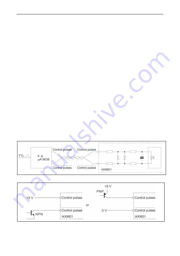
Preferably, the Control pulses and Direction inputs are energised with push-pull drivers.
This circuit offers high noise immunity.
Fig. 7: Push-pull control
Fig. 8: Open collector control


