Photon Focus MV1-D1024E User Manual Download Page 74

7 The PFRemote Control Tool

7.4

Installation Notes

Before installing the required software with the PFInstaller, make sure that your frame grabber
software is installed correctly.

Several DLLs are necessary in order to be able to communicate with the cameras:

PFCAM.DLL

: The main DLL file that handles camera detection, switching to specific camera

DLL and provides the interface for the SDK.

’CAMERANAME’.DLL

: Specific camera DLL

COMDLL.DLL

: Communication DLL. This COMDLL is not necessarily CameraLink

®

specific, but

may depend on a CameraLink

®

API compatible DLL, which should also be provided by

your frame grabber manufacturer.

CLALLSERIAL.DLL

: Interface to CameraLink

®

frame grabber which supports the clallserial.dll.

CLSER_USB.DLL

: Interface to USB port.

More information about these DLLs is available in the SDK documentation [SW002].

7.5

Graphical User Interface (GUI)

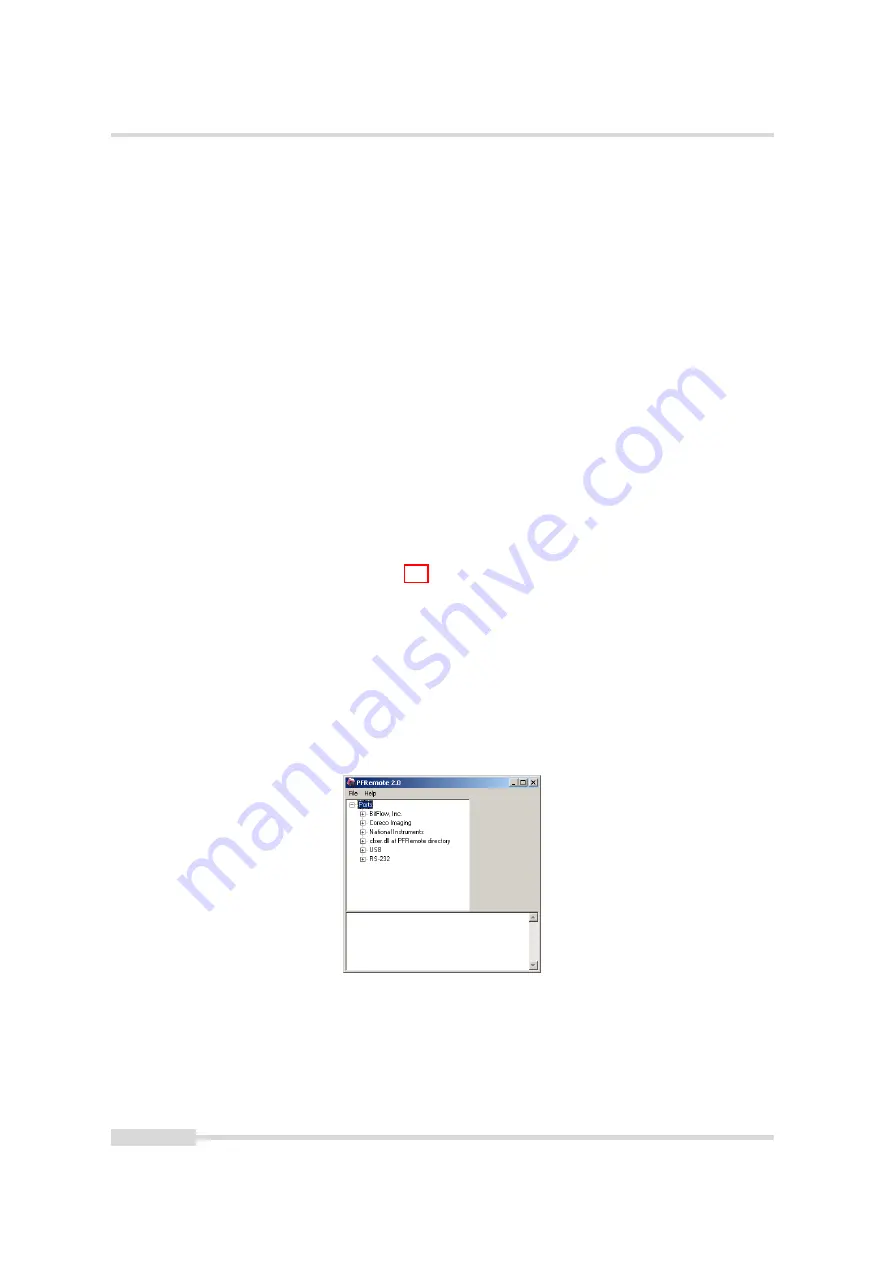
PFRemote consists of a main window (Fig. 7.2) and a configuration dialog. In the main window,
the camera port can be opened or closed, and log messages are displayed at the bottom. The
configuration dialog appears as a sub window as soon as a camera port was opened
successfully. In the sub window of PFRemote the user can configure the camera properties.

The following sections describe the general structure of PFRemote.

7.5.1

Port Browser

On start, PFRemote displays a list of available communication ports in the main window.

Figure 7.2: PFRemote main window with PortBrowser and log messages

To open a camera on a specific port double click on the port name (e.g. USB). Alternatively
right click on the port name and choose

Open & Configure...

. The port is then queried for a

compatible Photonfocus camera.

In the PFRemote main window, there are two menus with the following entries available:

74 of 109

MAN064 02/2020 V1.1

Summary of Contents for MV1-D1024E

Page 1: ...Photonfocus MV1 D1024E Camera Series CMOS camera with Camera Link interface MAN064 02 2020 V1 1...

Page 2: ...is assumed by Photonfocus AG for its use Photonfocus AG reserves the right to make changes to this information without notice Reproduction of this manual in whole or in part by any means is prohibite...

Page 3: ...Image Acquisition 21 4 1 1 Readout Modes 21 4 1 2 Constant Frame Rate CFR 23 4 2 Pixel Response 23 4 2 1 Linear Response 23 4 2 2 LinLog 24 4 2 3 Skimming 28 4 3 Reduction of Image Size 29 4 3 1 Regi...

Page 4: ...61 4 12 Configuration Interface CameraLink 64 5 Precautions 65 5 1 IMPORTANT NOTICE 65 6 Hardware Interface 69 6 1 Connectors 69 6 1 1 CameraLink Connector 69 6 1 2 Power Supply 69 6 1 3 Trigger and...

Page 5: ...0 1 Directives and General Standards 99 10 2 Country specific Information 99 10 2 1 For customers in the USA 99 10 2 2 For customers in Canada 100 10 2 3 Pour utilisateurs au Canada 100 10 3 Life supp...

Page 6: ...CONTENTS 6 of 109 MAN064 02 2020 V1 1...

Page 7: ...TRUCTIONS FOR USE BEFORE OPERATING THE CAMERA STORE THE INSTRUCTIONS FOR USE FOR FURTHER READING Photonfocus AG Bahnhofplatz 10 CH 8853 Lachen SZ Switzerland www photonfocus com info photonfocus com 4...

Page 8: ...1 55 451 00 00 Email support photonfocus com Table 1 1 Photonfocus Contact 1 4 Sales Offices Photonfocus products are available through an extensive international distribution network and through our...

Page 9: ...er rors 1 6 Legend In this documentation the reader s attention is drawn to the following icons Important note additional information Important instructions General warning possible component damage...

Page 10: ...1 Preface 10 of 109 MAN064 02 2020 V1 1...

Page 11: ...the system CameraLink cables can be purchased from directly Photonfocus www photonfocus com in some countries A suitable power supply A suitable power supply can be purchased at your Photonfocus deale...

Page 12: ...CameraLink cable see Fig 2 2 Figure 2 2 Camera with frame grabber power supply and cable Do not connect or disconnect the CameraLink cable while camera power is on For more information about CameraLi...

Page 13: ...ote on the support page at www photonfocus com 9 Install the camera software PFRemote Please follow the instructions of the PFRemote setup wizard Figure 2 3 Screen shot PFremote setup wizard 10 Start...

Page 14: ...2 How to get started CameraLink Figure 2 4 PFRemote start window 14 of 109 MAN064 02 2020 V1 1...

Page 15: ...igh resistance to blooming Extremely high image contrast achieved by LinLog technology Ideal for high speed applications global shutter Maximal frame rate at full resolution 150 fps Greyscale resoluti...

Page 16: ...look up tables 12 to 8 bit on user defined image region Region LUT Features Greyscale resolution 12 bit 10 bit 8 bit Region of Interest ROI Linear Mode LinLog Mode Skimming Up to 512 regions of intere...

Page 17: ...amera The housing and the pinout of the power connector and the CameraLink are identical The release of the MV1 D1024E 160 camera was required due to the non availability of some electronic components...

Page 18: ...A pixel 30 C Full well capacity 200 ke Spectral range 400 nm 900 nm Responsivity 120 x 103 DN J m2 610 nm 8 bit gain 1 Optical fill factor 35 Dynamic range up to 120 dB with LinLog Colour format monoc...

Page 19: ...nput range 5 15 V DC Max power consumption 4 0 W Lens mount C Mount CS Mount optional Dimensions 55 x 55 x 40 mm3 Mass 210 g Conformity CE RoHS WEEE Table 3 4 Physical characteristics and operating ra...

Page 20: ...for frame grabber configuration Footnotes 1 assuming 16 bit pixel data transmission CameraLink port and bit assignments are compliant with the CameraLink standard see CL Table 3 6 shows the tap config...

Page 21: ...e time of the next image can start during the readout time of the current image MV1 D1024E 160 CL Sequential readout available Simultaneous readout available Table 4 1 Available readout mode of MV1 D1...

Page 22: ...ault the camera continuously delivers images as fast as possible Free running mode in the sequential readout mode Exposure time of the next image can only start if the readout time of the current imag...

Page 23: ...FR When the CFR mode is switched on the target frame rate for the free running mode can be setting the frame time property Thus fewer images can be acquired than would otherwise be possible When Const...

Page 24: ...n region between linear and logarithmic response can be smoothly adjusted by software and is continuously differentiable and monotonic G r e y V a l u e L i g h t I n t e n s i t y 0 1 0 0 L i n e a r...

Page 25: ...m e 1 T i m e 2 m a x 1 0 0 0 Figure 4 8 Constant LinLog voltage in the Linlog1 mode 0 50 100 150 200 250 300 Typical LinLog1 Response Curve Varying Parameter Value1 Illumination Intensity Output gre...

Page 26: ...ution Fig 4 11 and Fig 4 12 show how the response curve is controlled by the three parameters Value1 Value2 and the LinLog time Time1 Settings in LinLog2 mode enable a fine tuning of the slope in the...

Page 27: ...igure 4 12 Response curve for different LinLog settings in LinLog2 mode LinLog3 To enable more flexibility the LinLog3 mode with 4 parameters was introduced Fig 4 13 shows the timing diagram for the L...

Page 28: ...dark areas of an image Skimming provides an adjustable level of in pixel gain for low signal levels It can be used together with LinLog to give a smooth monotonic transfer function from high gain at...

Page 29: ...ndow and is specified by its position within the full frame and its width and height Fig 4 16 gives some possible configurations for a region of interest and Table 4 2 shows some numerical examples of...

Page 30: ...139 139 fps 1 ms 130 140 fps 2 ms 115 140 fps 5 ms 85 140 fps 10 ms 60 99 fps 12 ms 53 82 fps Table 4 3 Frame rate of different exposure times sequential readout mode simultaneous readout mode resolut...

Page 31: ...ng ROIs are not allowed and no row must be read out more than once The individual ROI in a MROI must not overlap and no row should be included in more than one ROI Fig 4 17 compares ROI and MROI the s...

Page 32: ...4 Functionality Fig 4 18 shows another MROI drawing illustrating the effect of MROI on the image content Figure 4 18 Multiple Regions of Interest with 5 ROIs 32 of 109 MAN064 02 2020 V1 1...

Page 33: ...n the height of every ROI should be a multiple of 3 Fig 4 19 shows decimation on the full image The rows that will be read out are marked by red lines Row 0 is read out and then every nth row 0 0 x m...

Page 34: ...4 Functionality 0 0 x m a x y m a x R O I Figure 4 20 Decimation and ROI M R O I 0 R O I M R O I 2 M R O I 1 0 0 x m a x y m a x Figure 4 21 Decimation and MROI 34 of 109 MAN064 02 2020 V1 1...

Page 35: ...t of the elongation of an injection needle is given in Fig 4 23 In this application the height information is less important than the width information Applying decimation 2 on the original image on t...

Page 36: ...ve edge of the incoming trigger An additional trigger delay can be applied that delays the start of the exposure by a user defined time see Section 4 4 4 This often used to start the exposure after th...

Page 37: ...w e r T r i g g e r S o u r c e E X S Y N C C C 1 S o f t t r i g g e r C a m e r a L i n k T M F r a m e G r a b b e r F l a s h C a m e r a 2 D a t a C a m e r a L i n k E X S Y N C C C 1 S o f t t...

Page 38: ...ure time e x t e r n a l t r i g g e r p u l s e i n p u t t r i g g e r a f t e r i s o l a t o r t r i g g e r p u l s e i n t e r n a l c a m e r a c o n t r o l d e l a y e d t r i g g e r f o r s...

Page 39: ...the optional external strobe output is controlled by the rising edge of the trigger pulse Timing diagram Fig 4 28 shows the detailed timing for the external trigger mode with pulse width controlled ex...

Page 40: ...enabled it starts a predefined number of acquisitions after one single trigger pulse The time between two acquisitions and the number of acquisitions can be configured by a user defined value via the...

Page 41: ...o n t r o l i n t e r n a l s t r o b e c o n t r o l e x t e r n a l s t r o b e p u l s e o u t p u t t d i s o i n p u t t j i t t e r t t r i g g e r d e l a y t e x p o s u r e t s t r o b e d e...

Page 42: ...ra settings 0 41 s ttrigger offset non burst mode 100 ns duration of 1 row ttrigger offset burst mode 125 ns 125 ns texposure 10 s 0 41 s tstrobe delay 0 0 41 s tstrobe offset non burst mode 100 ns 10...

Page 43: ...ser can reset the Missed Trigger Counter Missed Burst Trigger Counter The missed burst trigger counter counts trigger pulses that were ignored by the camera in the burst trigger mode because they occu...

Page 44: ...g e S e n s o r D i g i t a l O f f s e t D i g i t a l G a i n L o o k u p t a b l e L U T C r o s s h a i r s i n s e r t i o n S t a t u s l i n e i n s e r t i o n T e s t i m a g e s i n s e r t...

Page 45: ...determined automatically in the camera Do not set any reference images when gain or LUT is enabled Read the follow ing sections very carefully Correction values of both reference images can be saved...

Page 46: ...essary to adjust the black level offset of the camera In the histogram of the black reference image ideally there are no grey levels at value 0 DN after adjustment of the black level offset All pixels...

Page 47: ...roper gain correction Gain correction algorithm After configuring the camera with a black and grey reference image the camera is ready to apply the gain correction 1 Determine the average value of the...

Page 48: ...ey reference image must be obtained at uniform illumination Use a high quality light source that delivers uniform illumination Standard illu mination will not be appropriate When looking at the histog...

Page 49: ...2 1 2 2 1 0 1 1 1 1 0 2 0 1 0 2 0 1 1 2 2 2 o f f s e t c o r r e c t i o n m a t r i x 1 1 2 1 0 9 1 1 2 2 0 9 1 1 1 1 0 8 1 1 0 1 3 0 8 1 0 1 1 2 2 2 g a i n c o r r e c t i o n m a t r i x c o r r...

Page 50: ...ey level transformation is remapping of the grey level values of an input image to new values The look up table LUT is used to convert the greyscale value of each pixel in an image into another grey v...

Page 51: ...T transfer curves 0 200 400 600 800 1000 1200 0 50 100 150 200 250 300 Grey level transformation Gain y 255 1023 a x x grey level input value 10 bit DN y grey level output value 8 bit DN a 1 0 a 2 0 a...

Page 52: ...s 0 200 400 600 800 1000 1200 0 50 100 150 200 250 300 Grey level transformation Gamma y 255 1023 x 1 x grey level input value 10 bit DN y grey level output value 8 bit DN 1 0 1 2 1 5 1 8 2 5 4 0 Figu...

Page 53: ...don t care LUT 0 is active on whole image X LUT 1 is active on whole image X X LUT 0 active in Region 0 X X X LUT 0 active in Region 0 and LUT 1 active in Region 1 LUT 0 supersedes LUT1 Table 4 6 LUT...

Page 54: ...U T 1 x 0 0 x 1 0 x 0 1 x 1 1 y 1 0 y 0 0 y 0 1 y 1 1 Figure 4 42 Overlapping Region LUT example L U T 0 L U T 1 L U T 1 L U T 0 0 0 0 0 x m a x y m a x x m a x y m a x Figure 4 43 Region LUT in keyh...

Page 55: ...and side The result of the application of the Region LUT is shown on the right hand side One Region LUT was applied on a small region on the lower part of the image where the brightness has been incre...

Page 56: ...4 45 shows two examples of the activated crosshairs with different grey values One with white lines and the other with black lines Figure 4 45 Crosshairs Example with different grey values The x and...

Page 57: ...s o l u t y a b s o l u t G r e y L e v e l R O I 0 0 x m a x y m a x R O I x a b s o l u t y a b s o l u t G r e y L e v e l R O I R O I x m a x y m a x Figure 4 46 Crosshairs absolute position MAN06...

Page 58: ...coming external triggers counter width 8 bit no wrap around see also Section 4 4 8 Missed burst trigger counter When the camera is in burst trigger mode see Section 4 4 5 a missed burst trigger counte...

Page 59: ...of ROI Window X 36 11 Horizontal end position of ROI Window X Window W 1 40 11 Vertical start position of ROI Window Y In MROI mode this parameter is the start position of the first ROI 44 11 Number o...

Page 60: ...togram only if the image width is a multiple of 1024 in 10 bit or 12 bit mode or 256 in 8 bit mode The height should be a multiple of 1024 In 12 bit mode 4 11 1 Ramp Depending on the configured grey l...

Page 61: ...of pixels of all grey values are the same Please refer to application note AN026 for the calculation and the values of the LFSR test image 4 11 3 Troubleshooting using the LFSR To control the quality...

Page 62: ...ximum length The maximal cable length depends on the frequency of the pixel clock At a pixel clock of 80 MHz a length of 8 m can be achieved with a good cable Also CameraLink cables may suffer either...

Page 63: ...mission errors CameraLink cables contain wire pairs which are twisted in such a way that the cable impedance matches with the LVDS driver and receiver impedance Excess stress on the cable results in t...

Page 64: ...stead the serial communication is usually routed through the frame grabber For some frame grabbers it might be necessary to connect a serial cable from the frame grabber to the serial interface of the...

Page 65: ...t use camera power supplies which meet the Limited Power Source LPS requirements If you use a powered hub or a powered switch in PoE or USB vision systems these devices must meet the LPS requirements...

Page 66: ...e is available on the Photonfocus website www photonfocus com To ensure that the examples will work properly in your application you must adjust them to meet your specific needs and must carefully tes...

Page 67: ...lectronic parts Avoid the generation of ESD during cleaning Take only a small amount of detergent to clean the camera body Keep in mind that the camera body complies to the IP40 standard Make sure the...

Page 68: ...5 Precautions 68 of 109 MAN064 02 2020 V1 1...

Page 69: ...w of the CameraLink camera The CameraLink interface and connector are specified in CL For further details including the pinout please refer to Appendix Appendix A This connector is used to transmit co...

Page 70: ...he internal ESD protection and the optocoupler In order to use the strobe output the internal optocoupler must be powered with 5 15 V DC The STROBE signal is an open collector output therefore the use...

Page 71: ...d the serial communication Data signals CameraLink data signals contain the image data In addition handshaking signals such as FVAL LVAL and DVAL are transmitted over the same physical channel Camera...

Page 72: ...c k C C S i g n a l s S e r i a l I n t e r f a c e F r a m e g r a b b e r C a m e r a L i n k Figure 6 3 CameraLink interface system The frame grabber needs to be configured with the proper tap and...

Page 73: ...an be controlled by PFRemote and PFLib respectively To grab an image use the software or the SDK that was delivered with your frame grabber Figure 7 1 PFRemote and PFLib in context with the CameraLink...

Page 74: ...available in the SDK documentation SW002 7 5 Graphical User Interface GUI PFRemote consists of a main window Fig 7 2 and a configuration dialog In the main window the camera port can be opened or clo...

Page 75: ...l of your frame grabber in the PFRemote directory and rename it to clser dll The PortBrowser will then indicate this DLL as clser dll at PFRemote directory After connecting the camera the device can b...

Page 76: ...mera and reset the configuration to the factory defaults 7 6 Device Properties Cameras or sensor devices are generally addressed as device in this software These devices have properties that are acces...

Page 77: ...he configuration dialog Figure 8 1 Frame rate and average value indication Frame Rate fps Shows the actual frame rate of the camera in frames per second Update To update the value of the frame rate cl...

Page 78: ...per second can be varied from almost 0 up to the maximum frame rate Thus fewer images can be acquired than would otherwise be possible When Constant Frame Rate is switched off the camera delivers imag...

Page 79: ...le the simultaneous readout mode Combination of property Trigger Interleave and property LinLog Mode is not available Combination of property Trigger Interleave and property Trigger LevelControlled is...

Page 80: ...nterest ROI is defined as a rectangle X Y W H where X X coordinate starting from 0 in the upper left corner Y Y coordinate starting from 0 in the upper left corner W Window width in steps of 8 pixels...

Page 81: ...n y direction and its height The width and the horizontal offset are specified by X and W settings The maximum frame rate in MROI mode depends on the number of rows and columns being read out Overlapp...

Page 82: ...te Interface Trigger The Trigger signal is applied to the camera by the CameraLink frame grabber I O Trigger The trigger signal is applied directly to the camera on the power supply connector Exposure...

Page 83: ...the input trigger edge to the rising edge of the strobe output signal Number of Burst Triggers Set the number of burst Burst Trigger Period ms Set the time between the burst in milliseconds Burst Trig...

Page 84: ...near feedback shift register pseudo random image The pattern depends on the grey level resolution Ramp Test image Values of pixel are incremented by 1 starting at each row The pattern depends on the g...

Page 85: ...de 2x Digital gain 2 4x Digital gain 4 8x Digital gain 8 Digital Offset Substracts an offset from the data Only available in gain mode Fine Gain The fine gain can be used to adjust the brightness of t...

Page 86: ...ransfer curve for contrast expansion This camera performs a 12 to 8 bit mapping so that 4096 input grey levels can be mapped to 256 output grey levels 0 to 4096 and 0 to 255 This camera support 2 LUT...

Page 87: ...coordinate of region LUT starting from 0 in the upper left corner W Region LUT window width in steps of 2 pixel H Region LUT window height Set to max ROI Set Region LUT window to maximal ROI X 0 Y 0 W...

Page 88: ...global shutter and the possibility to control the transition between linear and logarithmic mode See also the corresponding section in the camera manual There are 3 predefined LinLog settings availab...

Page 89: ...Skimming is a Photonfocus proprietary technology to enhance detail in dark areas of an image Skimming Skimming value If 0 Skimming is disabled See also the corresponding section in the camera manual M...

Page 90: ...at compensate for non uniformities caused by the sensor the lens or the illumination Off No correction Offset Activate offset correction Offset Hotpixel Activate offset and hot pixel correction Hotpix...

Page 91: ...hen on the Set Black Ref Button If only offset and hot pixel correction is needed it is not necessary to calibrate a grey image see Calculate Gain Correction The gain correction is based on a grey ref...

Page 92: ...ame of the connected camera Typecode Type code of the connected camera Serial Serial number of the connected camera FPGA Sensor Revision Firmware revision of built in FPGA on the sensor PCB of the con...

Page 93: ...gger or from I O trigger interface Missed Burst Trigger This is a counter for burst trigger pulses that were blocked because the burst trigger pulse was received during the last burst is not yet finis...

Page 94: ...8 Graphical User Interface GUI 94 of 109 MAN064 02 2020 V1 1...

Page 95: ...gainst vibration shock moisture and dust The original packaging protects the camera adequately from vibration and shock during storage and transport Please either retain this packaging for possible la...

Page 96: ...the screws is shown in Fig 9 2 The ring can now be screwn upwards or downwards by turning the lens 3 To adjust the back focus fully open the aperture of the lens and set the focus to infinite 4 Start...

Page 97: ...of the most common contaminants Workshop air supply is not appropriate and may cause permanent damage to the sensor 3 If further cleaning is required use a suitable lens wiper or Q Tip moistened with...

Page 98: ...HUBY 340 Q tips Hans J Michael GmbH Germany Methanol Fluid Johnson Matthey GmbH Germany Semiconductor Grade 99 9 min Assay Merck 12 6024 UN1230 slightly flammable and poisonous www alfa chemcat com 2...

Page 99: ...ts EN 61000 4 2 2009 Electronic discharge immunity tests EN 61000 4 3 2006 A1 2008 A2 2010 Radiated radio frequency electromagnetic field immunity test EN 61000 4 4 2012 Electrical fast transient burs...

Page 100: ...atus complies with the Class A limits for radio noise emissions set out in Radio Interference Regulations 10 2 3 Pour utilisateurs au Canada Cet appareil est conforme aux normes Classe A pour bruits r...

Page 101: ...sure that your warranty remains in force adhere to the following rules 1 Do not open the housing or destroy the warranty seal of the camera Touching internal electronic components of the camera may da...

Page 102: ...ctions in the corresponding chapter of this manual 9 Transport and store the camera in its original packaging only and protect the sensor and the lens mount with a camera body cap 10 Read the manual c...

Page 103: ...ote LinLog Photonfocus December 2002 AN007 Application Note Camera Acquisition Modes Photonfocus March 2004 AN008 Application Note Photometry versus Radiometry Photonfocus December 2004 AN010 Applicat...

Page 104: ...12 References 104 of 109 MAN064 02 2020 V1 1...

Page 105: ...ent of the power supply plug is given in Table A 2 It is extremely important that you apply the appropriate voltages to your camera Incorrect voltages will damage or destroy the camera Figure A 1 Powe...

Page 106: ...be signal Table A 2 Power supply plug pin assignment A 2 CameraLink Connector The pinout for the CameraLink 26 pin 0 5 Mini D Ribbon MDR connector is according to the CameraLink standard CL and is lis...

Page 107: ...12 I P_CC4 Positive LVDS Input Camera Control 4 CC4 13 PW SHIELD Shield 14 PW SHIELD Shield 15 O P_XD0 Positive LVDS Output CameraLink Data D0 16 O P_XD1 Positive LVDS Output CameraLink Data D1 17 O...

Page 108: ...A Pinouts 108 of 109 MAN064 02 2020 V1 1...

Page 109: ...Revision History Revision Date Changes 1 0 September 2014 First version 1 1 February 2020 Chapter CE Compliance updated chapter Precautions added new camera image inserted MAN064 02 2020 V1 1 109 of 1...

Reviews: