


6 Hardware Interface
Serial communication:
A CameraLink
®
camera can be controlled by the user via a RS232
compatible asynchronous serial interface. This interface is contained within the
CameraLink
®
interface and is physically not directly accessible. Refer to Section 5.8 for
more information.
Ca
m
er
aL
in
k
C a m e r a
I m a g e d a t a ,
F V A L , L V A L , D V A L
P i x e l C l o c k
C C S i g n a l s
S e r i a l I n t e r f a c e
F r a m e -
g r a b b e r
Ca
m
er
aL
in
k
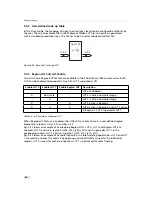
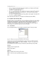
Figure 6.3: CameraLink interface system
The frame grabber needs to be configured with the proper tap and resolution settings,
otherwise the image will be distorted or not displayed with the correct aspect ratio. Refer to
Table 4.3 and to Section 4.6 for a summary of frame grabber relevant specifications. Fig. 6.3
shows symbolically a CameraLink
®
system. For more information about taps refer to the
relevant application note [AN021] on the Photonfocus website.
52
Summary of Contents for CameraLink MV1-D1280
Page 1: ...User Manual Photonfocus MV1 D1280 CameraLink Series CMOS Area Scan Camera MAN058 05 2013 V1 1...
Page 2: ......
Page 4: ...2...
Page 7: ...B Revision History 81 CONTENTS 5...
Page 8: ...CONTENTS 6...
Page 16: ...3 How to get started CameraLink Figure 3 4 PFRemote start window 14...
Page 24: ...4 Product Specification 22...
Page 72: ...8 Graphical User Interface GUI 70...
Page 74: ...9 Mechanical Considerations 72...
Page 76: ...10 Warranty 74...
Page 78: ...11 References 76...
Page 82: ...A Pinouts 80...


