


5.2.7
Software Trigger
The software trigger enables to emulate an external trigger pulse by the camera software
through the serial data interface. It works with both burst mode enabled and disabled. As
soon as it is performed via the camera software, it will start the image acquisition(s),
depending on the usage of the burst mode and the burst configuration. The trigger mode
must be set to
Interface Trigger
or
I/O Trigger
.
5.2.8
Missed Trigger Counters
Missed Trigger Counter
If an external trigger (interface trigger or I/O trigger) is applied while
the camera is not ready to accept a new trigger, a counter (Missed Trigger Counter) is
incremented and the trigger is rejected. The value of the Missed Trigger Counter can be
read out from a camera register (
Counter.MissedTrigge
r). When the Missed Trigger
Counter reaches its maximal value it will not wrap around. The user can reset the Missed
Trigger Counter.
Missed Burst Trigger Counter
The missed burst trigger counter counts trigger pulses that were
ignored by the camera in the burst trigger mode because they occurred while the camera
was not ready to accept a new trigger. To avoid this, the Burst Period Time must be
incremented so that the minimal frame time for the current settings is not violated. The
value of the Missed Burst Trigger Counter can be read out from a camera register
(Counter.MissedBurstTrigger). When the Missed Trigger Counter reaches its maximal value
it will not wrap around. The user can reset the Missed Burst Trigger Counter.
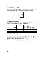
5.2.9
Strobe Output
The strobe output is an opto-isolated output located on the power supply connector that can
be used to trigger a strobe. The strobe output can be used both in free-running and in trigger
mode. There is a programmable delay available to adjust the strobe pulse to your application.
The strobe output needs a separate power supply. Please see Section Section
6.1.3 and Figure Fig. 5.11 and Fig. 5.12 for more information.
.
5.2 Trigger and Strobe
35
Summary of Contents for CameraLink MV1-D1280
Page 1: ...User Manual Photonfocus MV1 D1280 CameraLink Series CMOS Area Scan Camera MAN058 05 2013 V1 1...
Page 2: ......
Page 4: ...2...
Page 7: ...B Revision History 81 CONTENTS 5...
Page 8: ...CONTENTS 6...
Page 16: ...3 How to get started CameraLink Figure 3 4 PFRemote start window 14...
Page 24: ...4 Product Specification 22...
Page 72: ...8 Graphical User Interface GUI 70...
Page 74: ...9 Mechanical Considerations 72...
Page 76: ...10 Warranty 74...
Page 78: ...11 References 76...
Page 82: ...A Pinouts 80...


