


16
HELIX BOARD 12 PLUS
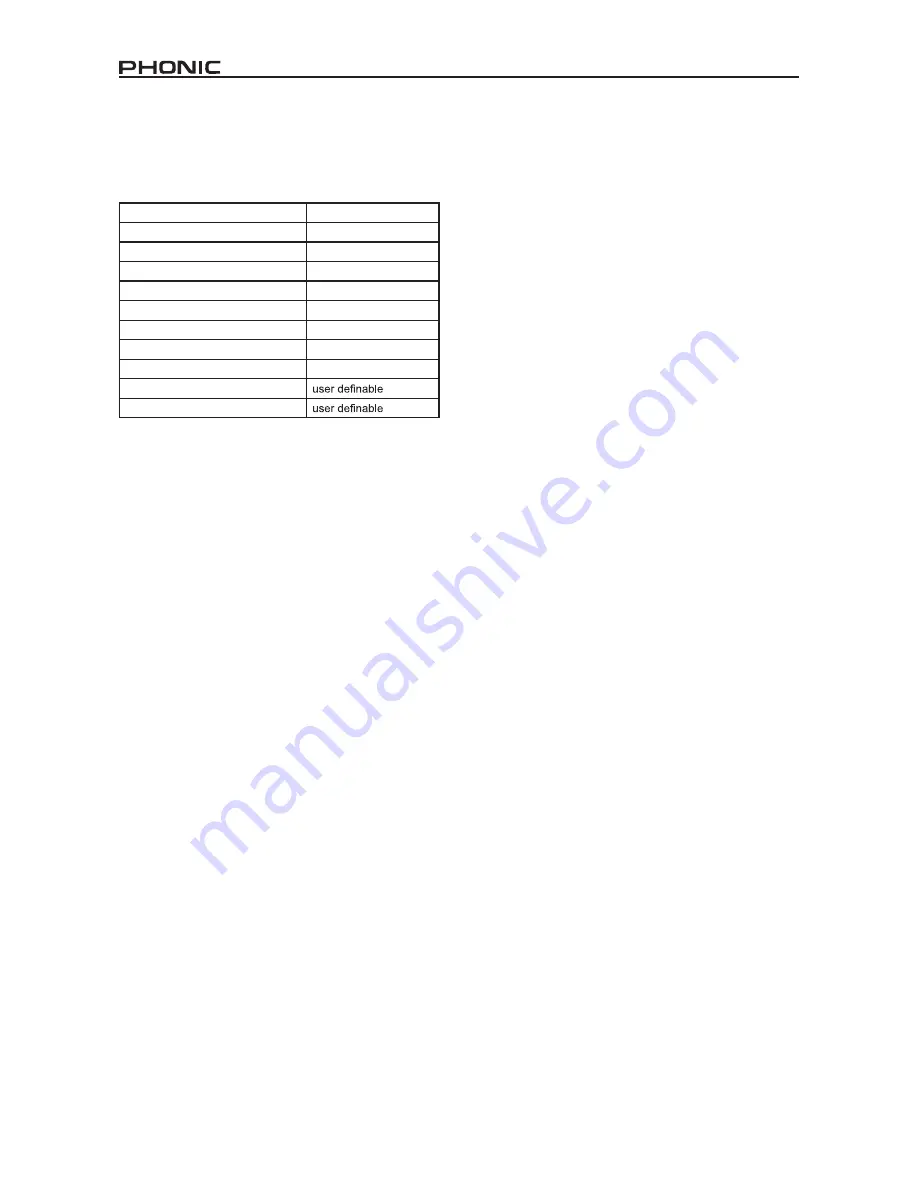
Channel Assignment
When using a Digital Audio Workstation on a PC, and within the
included Phonic Helix Board control panel software, the following
names have been attributed to the input channels of the Helix
Board.
If you would like to use the Helix Board as your default audio output
device on your PC, simply go into the Windows control panel and
select “Sound and Audio Devices.” Select the Audio tab, and use
the pull-down menu to select one of the Helix Board’s inputs from
the list of available output devices. The Helix Board can also be
selected as the default output device for individual programs by
editing said programs’ settings / options.
Operating With DAW Software
After successfully completing the installation process, the following
process must be followed to work efficiently with the Helix Board.
In the following example, we are using Cubase LE 4 (included
with the Helix Board 12 Plus) - however most other DAW software
should be similar.
1. Open the program.
2. Go to the ‘Devices’ pull-down menu and select ‘Device Setup’.
On the left, select ‘VST Multitrack’.
3. From the ASIO Driver drop-down list select the ‘Helix Board
ASIO Driver’. A pop-up box will ask you if you want to switch
to the ASIO driver. Click ‘Switch’. This completes the basic
setup.
4. The following steps should be followed to activate audio tracks
received from or sent by the Helix Board.
a.
Go to the “devices” pull-down menu and select ‘VST Inputs’.
This will display the various inputs (“Analog In 1”, “Analog
In 2”, etc.)
b.
Activate channels by clicking the “Active” button located next
to each channel name.
5. For further instructions on the operation of Cubase, please
consult the owner’s manual by pressing F1 while the program
is open.
If you wish to reset the Helix Board ASIO driver, simply go to
the ‘devices’ pull-down menu and select ‘device setup’. Simply
click ‘reset’ and select the ‘Helix Board ASIO Driver’. Click ‘ok’
to continue and the Helix Board should once again become
functional.
Computer Input Channel Name
Mixer Channel
HB 12 Plus CH 1
Channel 1
HB 12 Plus CH 2
Channel 2
HB 12 Plus CH 3
Channel 3
HB 12 Plus CH 4
Channel 4
HB 12 Plus CH 5
Channel 5 (Stereo L)
HB 12 Plus CH 6
Channel 6 (Stereo R)
HB 12 Plus CH 7
Channel 7 (Stereo L)
HB 12 Plus CH 8
Channel 8 (Stereo R)
HB 12 Plus Main L
HB 12 Plus Main R


