nized as an alarm. Once an alarm trips, the unit will begin its noti-
fication sequence (unless you are online through the serial port, in
which case you can acknowledge the alarm directly and cancel the
notification process). Listed below are definitions for each of the
parameters for programming the dry contact inputs.
Configuring the Input Name
The input
Name
is used to describe the condition being monitored.
It can be up to 16 characters.
Input Enable/Disable
A channel must be
Enabled
for the input to be read by the WTU-14.
When a channel is enabled its status will appear on the status screen
and on the web page.
Configuring the Input Type
The input
Type
can be either Normally Open or
Normally Closed.
When an input changes from its normal condition to the opposite
condition, the Pulse Count (if enabled) will increment, the Run
Timer (if enabled) will start running, and the Alarm Recognition
timer will start running (if alarms are enabled).
Configuring the Run Timer
The
Run Timer
can be used to track how long an input condition has
existed. This can be useful for monitoring pump or generator run
times. The value can be preset by clicking on the run time value on
the lower right part of the screen.
Configuring the Pulse Counter
The
Pulse Counter
can be used to track how many times a contact
closure has changed state. Other possibilities include: measuring
rainfall from a tipping bucket rain gauge or measuring liquid flow
from a pulsed output flow gauge. The maximum value of the Pulse
Counter (after the multiplier is applied) is 2 billion. Minimum Pulse
Width for Pulse Count: 50ms.
The
Pulse Count Multiplier
allows you to make each pulse equate to
a greater value. For example, suppose a flow gauge outputs a single
pulse for every 100 gallons. By setting the
Pulse Count Multiplier
Skymetry WTU-14
Manual
42
Summary of Contents for Skymetry WTU-14
Page 1: ...WTU 14 User s Manual version 1 11 Phonetics Inc LIT 0085...
Page 5: ...v...
Page 14: ...Skymetry WTU 14 Manual xiv...
Page 20: ...Skymetry WTU 14 Manual 20...
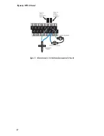
Page 32: ...Figure 11 A thermistor and a 4 20mA transducer connected to the unit Skymetry WTU 14 Manual 32...
Page 48: ...Skymetry WTU 14 Manual 48...
Page 52: ...Skymetry WTU 14 Manual 52...
Page 58: ...Skymetry WTU 14 Manual 58...
Page 64: ...Skymetry WTU 14 Manual 64...
Page 82: ...Skymetry WTU 14 Manual 82...
Page 86: ...Skymetry WTU 14 Manual 86...
Page 90: ...Skymetry WTU 14 Manual 90...
Page 98: ...Skymetry WTU 14 Manual 98...
Page 100: ...Skymetry WTU 14 Manual 100...
Page 106: ...Skymetry WTU 14 Manual 106...
Page 108: ...Skymetry WTU 14 Manual 108...
Page 109: ...Test Log...
Page 110: ......


