Ver. Phoenix 1.3 _ 01-09-2017
- 1 -
Phoenix Mixer India Pvt. Ltd.
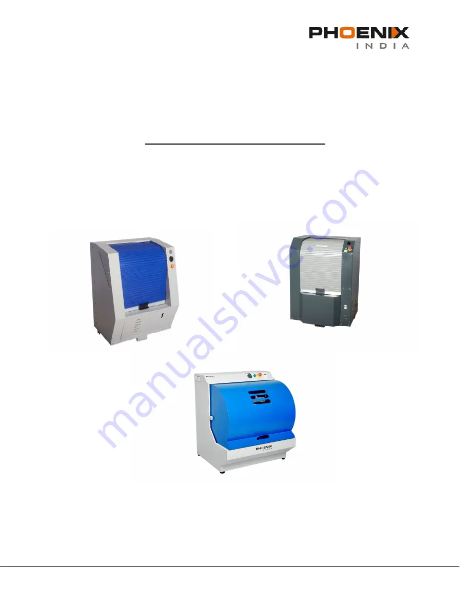
Gyro 525 / 600 / 1014
MANUAL GYROSCOPIC MIXER
Operating and Service Manual
© 2008 Phoenix Mixer India Pvt Ltd.
Page 1: ...Ver Phoenix 1 3 _ 01 09 2017 1 Phoenix Mixer India Pvt Ltd Gyro 525 600 1014 MANUAL GYROSCOPIC MIXER Operating and Service Manual 2008 Phoenix Mixer India Pvt Ltd ...
Page 2: ...enix Unless otherwise indicated all references to companies names data and addresses used in the screens and or examples are purely coincidental and serve only to clarify the use of the Phoenix Mixer Phoenix shall not be liable for technical or editorial errors or omissions made herein nor for incidental or consequential damages resulting from the performance or use of this material If you require...
Page 3: ...CIFICATIONS 11 6 INSTALLATION 14 7 CONTROLS 15 8 OPERATIONS 16 9 PREVENTIVE MAINTANCE 19 9 1 USE OF PLATFORM 9 2 REPLACMENT OF PARTS 9 3 TOOLS REQUIRED 9 4 REPLACING NEW CLAMPING LEVER AND SPRING 9 5 REPLACMENT OF BELTS 9 6 REPLACMENT OF RUBBER LINING 9 7 MINIMUM SPARES REQUIRED 10 MAINTANCE AND TROUBLE SHOOTING 24 11 SCHEMETIC DIAGRAM 26 12 REFERENCE LEGEND 27 ...
Page 4: ...CK MECHANISM In case of emergency press the Red Emergency Stop button Do not overload the machine Check that the weight and dimension of the mixing can are suitable Use only undamaged and sturdy Mixing Can If you don t the container may burst Never lift large and heavy Can into the machine The mixing Can has to be closed completely Make sure that the mixing Can sits in central position on Bottom D...
Page 5: ...yro 525 600 1014 has been designed to meet the demands of the retail market The dimension of the machine makes it versatile and suitable for use in all environments The unique design results in reduced maintenance and in color mixing at the lowest cost per liter produced Gyro 525 600 1014 is a rugged and reliable mixer which performance and design exhibits the qualities of a strong and sturdy engi...
Page 6: ...D 220 RPM 220 RPM CLAMPING MANUAL MANUAL DOOR PLASTIC SHUTTER WITH METAL BARS PLASTIC SHUTTER WITH METAL BARS MAIN MOTOR 0 5 HP 1PH 220 Vac 50 Hz 1440 RPM 0 5 HP 1PH 220 Vac 50 Hz 1440 RPM MAXIMUM NOISE LEVEL 55 Db 55 Db POWER SUPPLY 220 V 50 Hz 220 V 50 Hz POWER SUPPLY OPTIONAL 220 110 V 60 Hz 220 110 V 60 Hz TIMER MECHANICAL UPTO 5 MIN MECHANICAL UPTO 5 MIN LOCKING DOOR DEVICE Safety Door s w N ...
Page 7: ...RPM CLAMPING MANUAL MANUAL DOOR PLASTIC SHUTTER WITH METAL BARS PLASTIC SHUTTER WITH METAL BARS MAIN MOTOR 0 5 HP 1PH 220 Vac 50 Hz 1440 RPM 0 5 HP 1PH 220 Vac 50 Hz 1440 RPM MAXIMUM NOISE LEVEL 55 Db 55 Db POWER SUPPLY 220 V 50 Hz 220 V 50 Hz POWER SUPPLY OPTIONAL 220 110 V 60 Hz 220 110 V 60 Hz TIMER MECHANICAL UPTO 5 MIN MECHANICAL UPTO 5 MIN LOCKING DOOR DEVICE Safety Door s w N A AVAILABLE EL...
Page 8: ...SPIN SPEED 220 RPM 220 RPM CLAMPING MANUAL MANUAL DOOR METAL DOOR METAL DOOR MAIN MOTOR 0 5 HP 1PH 220 Vac 50 Hz 1440 RPM 0 5 HP 1PH 220 Vac 50 Hz 1440 RPM MAXIMUM NOISE LEVEL 55 Db 55 Db POWER SUPPLY 220 V 50 Hz 220 V 50 Hz POWER SUPPLY OPTIONAL 220 110 V 60 Hz 220 110 V 60 Hz TIMER MECHANICAL UPTO 5 MIN MECHANICAL UPTO 5 MIN LOCKING DOOR DEVICE Safety Door s w N A AVAILABLE ELECTRONIC N A BOARD ...
Page 9: ... parts of control Systems Part 1 General principles for design EN 1088 1995 Safety of machinery Interlocking devices associated with guards EN 294 1992 Safety of machinery Safety distances to prevent danger zones being reached by the upper limbs EN 953 1997 Safety of machines Guards General requirements for the design and construction of fixed and movable for coating materials PrEN 12757 1 Mixing ...
Page 10: ... foregone profit or other material losses on the part of the customer is expressly excluded Warranty and liability claims for personal or material damage are excluded if attributable to one or more of the following causes The part unit shall be returned with transportation charges prepaid If the fault has been caused by misuse or abnormal conditions of operation repairs will be billed at a normal ...
Page 11: ...E GROUNDED Attention Connect this product to a dedicated electrical circuit no other devices shall be connected to this circuit Do not use extension cords to connect this product Attention Only trained personnel shall be permitted access to the electrical wiring within the machine DO NOT USE THIS PRODUCT IF THE BACK PANEL IS NOT IN PLACE The machine is equipped with a power supply cable having the...
Page 12: ...ed must be kept free of exposed flames incandescent fixtures or other devices that might create sparks 6 It is recommended that a ventilation system guaranteed to maintain the concentration of dangerous vapors around electrical components at less than 30 be installed 7 When the Gyro 525 600 1014 is not being used for a period of time such as at the end of the work day ensure that it is empty no pa...
Page 13: ... electrical fires be readily accessible Safety devices The machine is equipped with the following safety devices Emergency Stop Button Door Lock and sensor optional Emergency Stop Button For safety reasons all users should know the location of the Emergency Stop button and how to use it The RED Emergency Stop push button is located on the Right Hand control panel on the top front of the mixer to t...
Page 14: ... circuit is available in the immediate vicinity The circuit shall be installed in accordance with local codes The receptacle shall be of a configuration appropriate for the voltage and current rating of the circuit INSTALLATION It is recommended that during the installation of the mixer protective gloves be worn in order to prevent hand injuries Unpack the Gyro 525 600 1014 Mixer Ensure the machin...
Page 15: ...Ltd 7 CONTROLS RIGHT HAND CONTROL PANEL SND RIGHT HAND CONTROL PANEL STD Emergency Push Button With Key LED Green Illuminated Green when shutter is Unlocked Mechanical Timer sets mixing time Emergency Push Button Without Key Mechanical Timer sets mixing time ...
Page 16: ... down and press it on the top of the can and then release the Handle for Clamping Bracket Now turn the two keys of the Locking Plastic 12 in clockwise direction in order to clamp the clamping bracket To put some extra pressure on the can fix the Fine clamping lever to the Plug for fine clamping lever 10 Close the Shutter 3 properly Set the time required to shake the can depending on the can size b...
Page 17: ...nd side the mixer near the top rear corner is ON CAN LOADING 1 Open the Gyro 525 600 1014 Mixer door to its fully open position 2 Ensure the Can Holder Assembly is in the vertical top dead center TDC position with the Clamp Mechanical Mechanism at the top 3 Referring to the illustrations open the Can Clamping Bracket as follows o Take up the Clamping bracket assembly fully by pressing Handle for c...
Page 18: ...he Mechanical timer to the appropriate position o Gyro will spin for the set time to mix the Paint Once the set time has expired Gyro Assembly will come to a stop To STOP the mixer during an emergency situation push the Emergency push button The door will unlock USE THE EMERCENCY PUSH BUTTON IN AN EMERGENCY SITUATION ONLY Note Always remove the can from the mixer after the mix cycle has been compl...
Page 19: ... Replacement of Parts After certain period may be in accidental break down or due to wear tear of part it will become essential to replace few spare parts 9 3 Tools Required Allen key set containing 3 16 5 16 4 mm 5 mm 6 mm 8 mm 10 mm and 14 mm Allen keys Fix spanner set containing spanners of 6 to 26 mm size Screw drivers 6 8 12 Monkey Pliers Circlip Pliers Internal External Nose pliers and Combi...
Page 20: ...ket Remove the Spring for clamping lever 20 from socket provided on Clamping Bracket as shown in fig 2 and fig 3 Two Clamping levers are fixed on bracket by locking pins Unscrew the Nylock nut 11 Remove locking pin Clamping lever Put new springs in socket also replace Clamping lever 21 with new one Screw the Locking Pin Assemble the handle by inserting the levers in the slots of the handle Again p...
Page 21: ...66 Fig 1 Fig 2 Fig 3 Insert the Screw Driver on the left side of the Main wheel 7 and pull the belt slightly outwards as shown in fig1 Now to remove the belt rotates the Main wheel clockwise To put the belt back pass the belt on the Main motor pulley and the Main wheel and rotate the Main Wheel clockwise as shown in fig 3 9 5 2 V belt 24 Bottom Disc to Fix Pulley Gyro 600 SPZ1750 Gyro 525 SPZ1400 ...
Page 22: ...V belt as explained in chapter 10 1 Insert the Screw Driver into the grooves of bottom disc and rotate the disc in opposite direction fig 2 Now to remove the belt from Guide pulley 25 fixed to Main wheel Fig 3 After removing belt from Guide pulley remove it from Main wheel While putting new belt insert it in the Main wheel first Then insert the belt in Pulley then insert it in the Oval shaped spac...
Page 23: ...r of disc Pull out damaged lining with the help of screwdriver Clean surface of disc by using emery paper Use adhesive to fix new lining Put the lining on disc match the holes of lining with disc Replace the lining of the Single adapter in the same manner 9 7 Minimum Spares Required 1 V Belt Polyurethane Belt Rope Belt 2 Clamping Lever and Spring for Clamping lever 3 Rubber lining for Top Disc 4 R...
Page 24: ...Lithium base Troubleshooting PROBLEM TROUBLE SHOOTING Machine is not turning on or Not rotate 1 Check the Mains supply 2 Check MCB Position it should be ON 3 Check the Power supply 4 Check plug or loose wire 5 Check Motor belts Machine vibrates during operation or Not remain stable 1 Check the floor on which machine has been installed 2 Check the floor surface it should be on plain surface 3 Other...
Page 25: ... Shafts and apply the general purpose grease Machine is giving shock while in operation 1 Check for proper grounding If the earthing is not proper consult an Electrician Timer Failure 1 Check Power ON 2 Rotate Timer Knob 3 Reset Knob Note Shutter will not open when the Power is OFF Adjusting Transmission Belts Remove Cover for Motor from the machine Check belt tension which should bend 5 10mm whil...
Page 26: ...Ver Phoenix 1 3 _ 01 09 2017 26 Phoenix Mixer India Pvt Ltd 11 SCHEMATIC DIAGRAM Gyro 525 600 1014 STD Gyro 525 600 1014 SND ...
Page 27: ...1 Plug For Fine Clamping Lever H G017 12 Nylock Nut M6 F H119 13 Lock for Clamping Assembly H A006 14 Top Disc H G024 15 Stopper For Guide Shaft H G043 16 Guide Shaft H G034 17 Clamping Bracket H G025 18 Bakelite Ball H O003 19 Fine Clamping Lever H G008 20 Can remover plate H B039 21 Spring for Clamping Lever F H133 22 Clamping Lever H G003 23 V Belt A 79 Main Wheel Motor Pulley F H129 24 V Belt ...
Page 28: ...17 28 Phoenix Mixer India Pvt Ltd THANK YOU Phoenix Mixer India Pvt Ltd Plot No 7 Collage Road Vadkun Dahanu Road 401602 Dist Palghar Maharashtra INDIA Phone 91 2528 221120 www phoenixmixer com An ISO 9001 2015 Certified Company ...