IL PB BK DI8 DO4/EF-PAC
3-6
PHOENIX CONTACT
7725_en_01
–
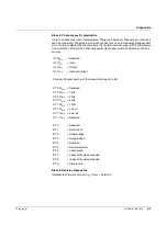
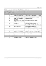
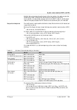
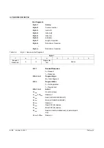
<Slot>:
The slot of the device to be addressed in the station. The bus coupler is addressed with
slot = 0, the integrated DI8/DO4 terminals are addressed with slot = 1. Starting with the
first connected device, the devices are addressed with slots 2 to 63.
–
<DP/V1 index>:
For access to the PCP objects of the local bus devices, PROFIBUS index 47
dec
(=
2F
hex
) is to be used. The PCP index is transmitted as part of the data field. For access
to the bus coupler, the object index can be used directly.
–
<DP/V1 length>:
For write access, the length of the subsequent data is specified here, and for read
access, the length of the expected data is specified. On a response, this parameter
contains the actual length of the DP/V1 data.
–
<Error decode>:
80
hex
indicates an error in DP/V1.
–
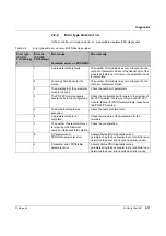
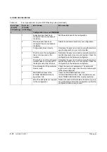
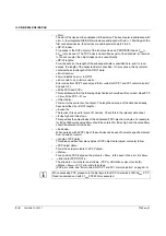
<Error code 1> and <Error code 2>:
Error codes from DP/V1 access (see "Error codes for DP/V1 and VC1 communication"
–
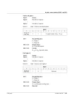
<Write PCP/read PCP>:
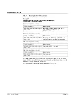
This specifies whether the following object indices should be written or read. Read PCP
= 06
hex
; Write PCP = 07
hex
.
–
<Object data>:
This is only the contents of an object. The length and scope of the data has already
been described by <DP/V1 length>.
–
<Invoke ID>:
The Invoke ID is used for some I/O devices. Check this in the relevant data sheet.
–
<Index high and Index low>:
This specifies the object index of the addressed PCP object in two bytes. For example,
for index 2300
hex
the value 23
hex
should be entered for Index high and the value 00
hex
should be entered for Index low.
–
<Subindex>:
When working with a PCP object, the subindex can be used to select a specific element
from an array or record.
–
<Length of PCP data>:
This value specifies how many bytes of PCP object data (object contents) follow.
–
<PCP object data>:
This is the actual contents of a PCP object.
–
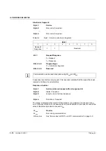
<Status>:
For a positive PCP response, the status is = 00
hex
, in the event of an error it is 44
hex
.
–
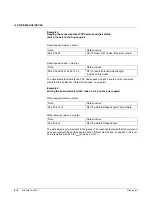
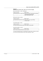
-<Error data (PCP/DP/V1)>:
The structure of error data is as follows, <PCP confirmation code> <Invoke ID>
<Status = 44
hex
> <PCP error code (4 bytes)>.
(PCP error code, see "Error codes for DP/V1 and VC1 communication" on page A-3).
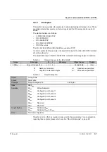
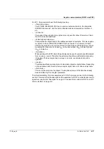
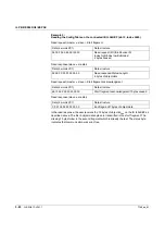
When accessing PCP, please note the first byte in the DP/V1 data block. With 06
hex
, PCP
Read is executed and with 07
hex
PCP Write is executed.


