IL PB BK DI8 DO4/EF-PAC
4-10
PHOENIX CONTACT
7725_en_01
Access via index 7
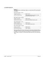
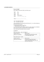
Please observe the structure of index 7 when accessing it:
In this example there are 7 connected terminals. Terminals 1, 2, 3, 4, and 7 should be active.
Terminals 5 and 6 are inactive.
The resulting data for object 7 is as follows:
08
hex
, 00
hex
, 07
hex
, 01
hex
, F2
hex
As the fourth byte for index 7 contains the length, the number of bytes to be transmitted is
only as many as required for the terminals to be activated/deactivated.
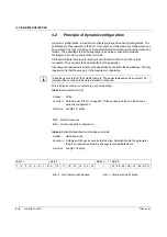
These 5 data bytes are described below as an example:
4 words VC1
Byte 1
08
hex
Byte 2
00
hex
Byte 3
07
hex
Byte 4
Length of data n
Byte 5
1
2
3
4
5
6
7
8
...
Byte 4+n
x
x
x
x
x
x
x
x
Bit = 0: Terminal and slot inactive
Bit = 1: Terminal and slot active
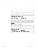
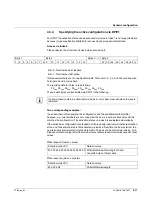
Write request (master -> slave) - Start fragment
Data (4 words VC1)
Data structure
08 00 07 01 F2 I 00 00 00
Read/write/Index high/Index low/Length/
1 byte of data/3 bytes unused
Write response (slave -> master)
Data (4 words VC1)
Data structure
88 00 02 05 F2 I 00 00 00
Read/write response/Status/Length/
Number of available terminals/Status of the
terminals/3 bytes unused

