


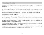
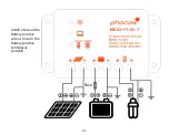


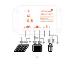

Connecting and Grounding
WARNING:
When the photovoltaic (solar) array is exposed to light, it supplies a dc voltage to this
equipment.
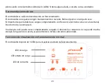
Connect wires in order indicated 1 2 3 4 5 6 to avoid installation faults.
To avoid any voltage on the wires, first connect the wire to the controller, then to the battery, panel or
load.
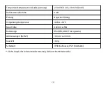
Recommended minimum wire size: ECO-N-10-T: 3.0mm
2
(AWG 12); ECO-N-20-T: 6.0mm
2
(AWG 10)
Use minimum 75°C stranded copper wire.
Make sure the wire length between battery and controller is as short as possible.
Be aware that ECO-N-T is designed for use in negative ground systems. If any grounding is required,
always do this on the negative wires.
The photovoltaic maximum current as defined in the National Electrical Code, clause 690.8 must not
exceed the rated charge current of the controller.
The photovoltaic maximum voltage as defined in the National Electrical Code, clause 690.7 cannot
exceed 30VDC (12V system) and 50VDC (24V system).
Wiring methods in accordance with the National Electrical Code, ANSI/NFPA 70 are to be used. Wiring
methods used shall be in accordance with the Canadian Electrical Code, Part I.
20
Summary of Contents for ECO-N-T Series
Page 6: ...4 Sicher ung...
Page 16: ...14 ECO N T Sicherer Betriebsbereich Nennlaststrom...
Page 35: ...33 Fusi ble...
Page 45: ...43 ECO N T SOA Safe Operating Area Corriente consumo nominal...
Page 65: ...63 Fus vel...
Page 75: ...73 SOA rea de prote o segura do ECO N T Corrente nominal consumidor...
Page 77: ...ECO N T LED IP68 IP21 ECO N T 75...
Page 78: ...CE CE 12 24 V 76...
Page 79: ...1 2 3 4 mm2 ECO N T 1 5 ECO N T 10 15A ECO N T 20 30 A 77...
Page 80: ...78...
Page 81: ...12 24 V ECO N T GEL AGM 79...
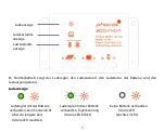
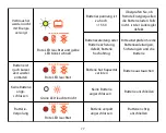
Page 82: ...3 LED LED LED LED 80 LED LED LED...
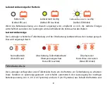
Page 83: ...LED LED LED LED LED LED LED 11 0 22 0 V 12 8 25 6 V 81...
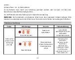
Page 84: ...LED 1 2 3 4 30 V 30 V 15 5 V 1 2 4 6 3 4 200 3 s 82...
Page 85: ...LED LED LED LED LED 15 5 V 83...
Page 86: ...LED LED LED 84...
Page 89: ...87 ECO N T SOA...


