background image

EN21

WelcomeEye Connect 2 / Touch / V1

1
2

3

4

5

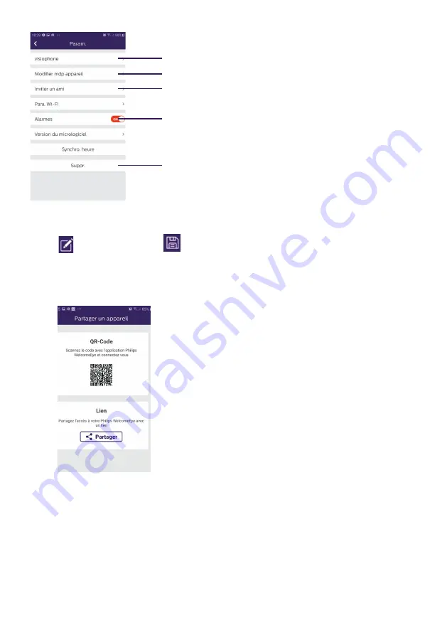
1. Used to rename your videophone.

Note:


used to modify and 

used to validate.

2. Used to change the password (stream and opening command)

3. Invite a friend


QR Code: This QR code allows your friends or family 
to simply connect to your Philips WelcomeEye 
Connect 2 videophone. See Chapter "

Add a 

smartphone to a connected videophone

".

Link: Share your Philips WelcomeEye Connect 2 
videophone login details with friends and family. 
• Have your friends download the Philips 
WelcomeEye application
• Share the link using the messaging service of your 
choice by pressing ‘

Partager

’ (Share)

• Securely share your password. 
• When you click on the link, your friend's 
WelcomeEye Connect application will automatically 
open and all the information on the videophone will 
be pre-populated
• The application asks you to enter the password 
you have already chosen
• Your friend is now connected to your videophone

4. Enables or disables call notifications.

Summary of Contents for WelcomeEye Connect 2

Page 1: ...User manual Video doorbell WelcomeEye Connect 2 WelcomeEye Touch V1 ...

Page 2: ...DP 5 8 1 0 2 3 Made in P R C Avidsen 19 avenue Marcel Dassault 37200 TOURS FRANCE DES 9901 VDP 5 1 0 0 6 3 1 2 3 4 5 6 1 2 7 8 1 2 1 2 DES 9901 VDP 5 1 0 0 6 3 Made in P R C IP44 20V 110mA RFID 125kHz 120 m max Of On Master On ZZZ Off Off Off ZZZ 1 2 Avidsen 19 avenue Marcel Dassault 37200 TOURS FRANCE ...

Page 3: ...4 Wifi 2 4GHz DES 9901 VDP 5 8 1 0 2 3 Made in P R C DES 9901 VDP 5 1 0 0 6 3 1 2 3 4 5 6 1 2 7 8 1 2 1 2 DES 9901 VDP 5 1 0 0 6 3 Made in P R C IP44 20V 110mA RFID 125kHz 120 m max Of On Master On Z Z Z On Master On On Z Z Z Of On Master On Z Z Z On Slave On On Z Z Z Of On Master On Z Z Z On Slave On On Z Z Z 1 2 1 2 1 Avidsen 19 avenue Marcel Dassault 37200 TOURS FRANCE Avidsen 19 avenue Marcel D...

Page 4: ...4V 550mA 1 3 2 4 Wifi 2 4GHz DES 9901 VDP 5 8 1 0 2 3 Made in P R C DES 9900 VDP 5 8 1 0 2 3 24V 550mA 1 3 2 4 Wifi 2 4GHz DES 9901 VDP 5 8 1 0 2 3 Made in P R C Of On Master On Z Z Z On Master On On Z Z Z Of On Master On Z Z Z On Slave On On Z Z Z Of On Master On Z Z Z On Slave On On Z Z Z Of On Master On Z Z Z On Master On On Z Z Z Of On Master On Z Z Z On Slave On On Z Z Z Of On Master On Z Z Z O...

Page 5: ...g the main or additional intercom panel 5 Installing a camera optional 6 MONITOR INTERFACE p 9 A Monitoring function and response to a call B Intercom function C Settings D Photo album E Video album 7 USER GUIDE p 14 8 SMARTPHONE APPLICATION p 15 9 TECHNICAL CHARACTERISTICS p 22 10 ACCESSORIES p 23 11 FAQ p 24 12 TECHNICAL ASSISTANCE WARRANTY p 27 13 SAFETY PRECAUTIONS p 28 14 FCC CE WARNING p 29 ...

Page 6: ...s items should be dismantled by an authorised technician only Safety measures To operate this system in complete safety it is essential that installers users and technicians follow all the safety procedures described in this manual Specific warnings and warning symbols are given for items where necessary 2 KIT CONTENTS 5 Plug in power supply 1 7 monitor 2 Wall bracket 3 Intercom panel 4 5 RFID bad...

Page 7: ...omeEye technology allows you to share the intercom panel between 2 families Each family can own up to three monitors The system can operate up to one camera and two intercom panels per family For effective usage please carefully read this instruction manual 4 NOMENCLATURE Monitor Touch screen Power supply terminal block Terminal block for connection to the intercom panel and accessories Loudspeake...

Page 8: ...IP44 20V 110mA RFID 125kHz Avidsen 19 avenue Marcel Dassault 37200 TOURS FRANCE DES 9901 VDP 5 1 0 0 6 3 1 2 3 4 5 6 1 2 7 8 1 2 1 2 DES 9901 VDP 5 1 0 0 6 3 Made in P R C IP44 20V 110mA RFID 125kHz Avidsen 19 avenue Marcel Dassault 37200 TOURS FRANCE DES 9901 VDP 5 1 0 0 6 3 1 2 3 4 5 6 1 2 7 8 1 2 1 2 DES 9901 VDP 5 1 0 0 6 3 Made in P R C IP44 20V 110mA RFID 125kHz Avidsen 19 avenue Marcel Dass...

Page 9: ...uble wires to increase the wire size a Connecting the videophone monitor intercom panel and camera Wires to be used 2 wires 0 75 mm2 up to 80 m long or 2 wires 1 5 mm2 up to 120 m long Ensure proper connection of the wires following one of the wiring diagrams depending on the desired configuration Be sure to refer to the labelling on the back of the monitor and the back of the intercom panel Confi...

Page 10: ...r badges 1 Swipe the blue badge four long beeps confirm the activation of the programming mode 2 Swipe all user badges grey to be activated one short beep confirms the programming of every badge presented 3 Once all of the badges have been programmed wait 10 seconds One long beep confirms the end of the programming process 3 Remove one or more user badges 1 Swipe the badge red 4 long beeps confirm...

Page 11: ... 1 2 4 7 5 6 3 1 Position the wall bracket so that the screen of the monitor is approximately 1 60m above the ground 2 Mark the location of the holes using the U bolt 3 Drill 4 Use pegs adapted to the bracket those supplied are suitable for solid walls 5 Attach the wall bracket 6 Connect the two intercom panel wires and the two power supply wires following the wiring diagram 7 Position the monitor...

Page 12: ...ntercom panel 2 Tip the intercom panel cover forward 3 The intercom s lens should be approximately 1 60m above the ground 4 Mark the locations 5 Drill 6 Use pegs adapted to the nature of the support the screws supplied are suitable for solid walls 7 Connect the two wires from the monitor and if necessary connect the electric strike plate and the gate see section 1 Wiring Configure the switches at ...

Page 13: ...r 5 Installing a camera optional Connect the wires in accordance with the wiring diagram Choose a suitable place to install the camera Ensure that nothing gets in the way of the installation Screw the wall section with the screws provided for solid walls Point the camera in the desired direction and tighten the retainer screw Configure the monitor s On 6 MONITOR INTERFACE Main Menu Lightly touch t...

Page 14: ...n the gate 5 To take a photo or video in accordance with the settings selected B Intercom function 1 2 Function only valid if an additional monitor is connected and the parameters are set correctly 1 To exit the function 2 Allows you to call the other monitors in the family answer when you receive a call from another monitor or hang up C Settings The settings menu consists of three pages for Welco...

Page 15: ...o configuration valid if photo mode has been selected Choose the number of photos taken 1 2 or 3 during a missed call or in monitoring mode 4 Deactivating silent mode This function turns off the monitor ringtone for a certain period snooze etc The monitor s LEDs will continue to flash to signal a call a b c a activate On deactivate Off silent mode monitor b Time when the ringtone will be deactivat...

Page 16: ...s one monitor choose Off d Activating energy saving mode of the videophone When the energy saving mode is activated On the product s energy consumption is reduced The intercom panel is placed on standby therefore the monitor no longer receives calls 7 Audio settings a b c d e a Choice of ringtone during a call from intercom panel 1 b Choice of ringtone during a call from intercom panel 2 only if a...

Page 17: ...ngs b date applies to the main menu only and time format settings Slide the image to access this menu 11 Reset menu a Micro SD card resetting and formatting May be necessary when using a micro SD card for the first time b Internal memory reset c Resetting the product to factory settings and returning to default settings visit memory function video and photo recording setup disabling ring tone answ...

Page 18: ... with them After two minutes of conversation the call ends and the screen returns to the home page If the conversation ends before the two minute timeout press the button to end the call The screen returns to the home page To refresh the picture press on the home screen To initiate another two minute conversation press the button Control an electric lock or strike plate by pressing the button Cont...

Page 19: ...e the answering system function is only possible if the video recording is activated Standby The screen is automatically placed on standby which means the screen enters sleep mode for energy saving and screen sustainability purposes If the monitor is on a menu other than the main one it automatically switches to the main screen after 15 seconds of inactivity If the monitor is on the main menu it a...

Page 20: ...omeEye Connect 2 Touch V1 4 From the WelcomeEye application click on to add a device 5 Click on new device and then next The application tells you where to find the QR Code that you will need to scan Click next ...

Page 21: ... to which your phone is connected appears To change it click on change WiFi If no network appears your phone is probably in 3G 4G When the WiFi 2 4GHz network you want appears enter the password Your mobile phone emits a sound that allows it to connect to your videophone Place your phone next to the monitor microphone ...

Page 22: ... customise your password Note you will be asked for the password every time you wish to open your electric strike plate or gate from the application Add a smartphone to a connected videophone 1 Download the Philips WelcomeEye application to your smartphone from the Apple store or Play store Note Disable the smartphone s WiFi smart network mode if it is activated 2 From the WelcomeEye application c...

Page 23: ...D information available in the WiFi settings and password Important When you click on the QR Code to the right of the UID line you will be able to scan the videophone monitor s QR Code and get its UID faster Click on Save If the videophone is not nearby you can scan the barcode in the WelcomeEye Connect 2 owner s application The barcode is available under the menu Invite a friend in the already co...

Page 24: ...age the camera settings name password WIFI network Channel number and alarm Activate deactivate the sound Take a video Take a photo This icon only appears when you have installed an addi tional camera or an additional panel You can choose to display the video stream from the additional camera or the intercom panel Full screen mode Open the electric strike plate or the gate Press and hold to speak ...

Page 25: ...your Philips WelcomeEye Connect 2 videophone login details with friends and family Have your friends download the Philips WelcomeEye application Share the link using the messaging service of your choice by pressing Partager Share Securely share your password When you click on the link your friend s WelcomeEye Connect application will automatically open and all the information on the videophone wil...

Page 26: ...CHARACTERISTICS Monitor ref 531038 WelcomeEye Connect 2 ref 538101 WelcomeEye Touch 2 wires 7 touch screen Resolution 800 x 480 Class 10 micro SD card up to 32GB not supplied IEEE 8111 b g n 2 4 GHz WiFi WelcomeEye Connect 2 only Radio power emitted 18 dB maximum Current consumption 550mA Connect 2 470mA Touch Power consumption 13 2W Connect 2 11 3W Touch 6 ringtones 85dB Dimensions 142 h x 210 l ...

Page 27: ... 7 screen Resolution 800 x 480 Current consumption 460mA Power consumption 11 1W 6 ringtones 85dB Dimensions 142 h x 210 l x 15 d mm WelcomeEye AddCompact additional monitor ref 531005 2 wires 4 3 screen Resolution 480 x 272 Current consumption 400mA Power consumption 9 6W 6 ringtones 85dB Dimensions 116 h x 146 w x 16 d mm WelcomeEye Outdoor Additional intercom panel ref 531006 C MOS colour senso...

Page 28: ... 2 Touch instructions available on the www philips com website for more information 11 FAQ Failure Cause Solution The monitor will not turn on The monitor is not receiving power Verify that the power supply is properly connected and turned on Check the polarity on the monitor or at the power supply output Poor connection or short circuit on the line Resolve the connection problem Does not work whe...

Page 29: ... panel for single family use Energy saving mode activated page 12 Poor picture and or sound Environment Check that the wires used have the right gauge and that the connection wires for the videophone are not in the same sheath as the 230VAC wires Purple picture Connection The connection cable must not be tangled Image is too bright Camera position Do not expose the lens of the camera directly to s...

Page 30: ...rify that the additional monitor is connected to 1 and 2 of the intercom panel for single family operation The additional intercom panel is not working Configuration Verify the position of switch 1 on the panels page 6 it must be different Don t forget to turn the power off for five seconds to activate the new settings Configuration menu of the monitors Verify that the monitors are valid BOTH of t...

Page 31: ...ing of the gate is not Configuration In application settings verify that code verr 2 Reminder the command can only be sent if a conversation via the intercom is ongoing Electric strike plate or lock does not work The electric strike plate or lock that you install must be equipped with a mechanical memory The strike plate current cannot exceed 1 1A Directly connect the strike plate or lock wires to...

Page 32: ...t scratches Clean with a soft cloth only no solvents The warranty is void if parts have been dismantled Before cleaning disconnect the equipment or switch it off at the mains Note Do not use any carboxylic acid alcohol or similar chemicals on the product In addition to damaging your device the fumes are also hazardous to your health and are explosive Do not use any tool that can conduct voltage wi...

Page 33: ...tructions for use of any other devices connected to the system Please contact an experienced person if you have any doubts regarding equipment operation or safety Never plug in or unplug electrical equipment with wet hands When installing this product check that the power supply cables are not at risk of being damaged Never replace damaged electrical cables yourself In this case remove them and ca...

Page 34: ...y one of the following methods Redirect or move the receptor antenna Increase the distance between the equipment and the receptor Connect the equipment to a socket belonging to a different circuit from the one to which the receptor is connected 15 DECLARATION OF COMPLIANCE The undersigned CFI Extel declares that the WelcomeEye radioelectric equipment complies with the 2014 53 EU directive The full...

Reviews: