background image

6-11

6-11

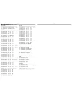
ELECTRICAL PARTS LIST - FRONT BOARD

ELECTRICAL PARTS LIST - FRONT BOARD

MISCELLANEOUS

1200

2422 025 14526

Flex Connector 16P

1201

4822 265 11553

Flex Connector 19P

1203

2422 025 14518

Flex Connector 9P

1204

4822 267 10731

Flex Connector 6P

1212

2422 025 14518

Flex Connector 9P

1213

4822 267 10731

Flex Connector 6P

1223

4822 265 11207

Flex Connector 6P

1224

4822 265 11531

Flex Connector 9P

1304

4822 265 11183

Flex Connector 4P

1400

4822 276 13775

Tact Switch

1401

4822 276 13775

Tact Switch

1402

4822 276 13775

Tact Switch

1403

4822 276 13775

Tact Switch

1404

4822 276 13775

Tact Switch

1405

4822 276 13775

Tact Switch

1406

4822 276 13775

Tact Switch

1407

4822 276 13775

Tact Switch

1408

4822 276 13775

Tact Switch

1409

4822 276 13775

Tact Switch

1410

4822 276 13775

Tact Switch

1411

4822 276 13775

Tact Switch

1412

4822 276 13775

Tact Switch

1413

4822 276 13775

Tact Switch

1414

4822 276 13775

Tact Switch

1415

4822 276 13775

Tact Switch

1416

4822 276 13775

Tact Switch

1417

4822 276 13775

Tact Switch

1418

4822 276 13775

Tact Switch

1419

4822 276 13775

Tact Switch

1601

2422 026 05059

Headphone Socket

1611

2422 129 16501

Rotary Encoder 12P

1616

2422 129 16835

Switch Jog-Shuttle

1700

2422 025 14526

Flex Connector 16P

1701

2422 025 14526

Flex Connector 16P

CAPACITORS

2100

4822 126 14249

560pF 10% 50V

/22

2101

4822 122 33197

1nF 10% 50V

/22

2102

4822 126 14226

82pF 5% 50V

/22

2103

4822 126 11785

47pF 5% 50V

/22

2104

2238 586 59812

100nF 50V

/22

2105

4822 126 14249

560pF 10% 50V

/22

2106

4822 126 14491

2,2uF 10V

/22

2107

4822 122 33761

22pF 5% 50V

2108

2020 552 94427

100pF 5% 50V

2109

2020 552 94427

100pF 5% 50V

2110

4822 122 33761

22pF 5% 50V

2111

2020 552 94427

100pF 5% 50V

2114

4822 122 33741

10pF 10% 50V

2115

4822 122 33741

10pF 10% 50V

2300

3198 017 41050

1uF 10V

2301

3198 017 41050

1uF 10V

2400

2238 586 59812

100nF 50V

2401

4822 124 80483

47uF 20% 6,3V

2402

2238 586 59812

100nF 50V

2403

4822 124 80483

47uF 20% 6,3V

2404

2238 586 59812

100nF 50V

2405

4822 124 80483

47uF 20% 6,3V

2406

2238 586 59812

100nF 50V

2407

4822 124 80483

47uF 20% 6,3V

2408

4822 122 33761

22pF 5% 50V

2409

4822 122 33752

15pF 5% 50V

2410

4822 122 33761

22pF 5% 50V

2411

4822 122 33761

22pF 5% 50V

2412

4822 122 33761

22pF 5% 50V

2413

4822 122 33741

10pF 10% 50V

2414

4822 122 33741

10pF 10% 50V

2423

5322 126 11583

10nF 10% 50V

2424

3198 017 44740

470nF 10V

2425

5322 126 11583

10nF 10% 50V

2428

2238 586 59812

100nF 50V

2430

4822 124 80483

47uF 20% 6,3V

2431

5322 126 11583

10nF 10% 50V

2432

2020 552 96305

4,7uF +80/-20% 10V

2433

2020 552 96305

4,7uF +80/-20% 10V

2434

2020 552 96305

4,7uF +80/-20% 10V

2435

4822 122 33741

10pF 10% 50V

2436

4822 122 33741

10pF 10% 50V

2440

2020 552 96305

4,7uF +80/-20% 10V

2441

4822 126 14238

2,2nF 50V

2461

2020 552 94427

100pF 5% 50V

2463

5322 126 11583

10nF 10% 50V

2464

5322 126 11583

10nF 10% 50V

2566

4822 122 33761

22pF 5% 50V

2567

4822 122 33761

22pF 5% 50V

2568

4822 122 33761

22pF 5% 50V

2569

4822 122 33761

22pF 5% 50V

2570

4822 122 33761

22pF 5% 50V

2571

4822 122 33761

22pF 5% 50V

2572

4822 122 33761

22pF 5% 50V

2573

4822 122 33761

22pF 5% 50V

2574

4822 122 33761

22pF 5% 50V

2575

4822 122 33761

22pF 5% 50V

2576

4822 122 33761

22pF 5% 50V

2577

4822 122 33761

22pF 5% 50V

2578

4822 122 33761

22pF 5% 50V

2604

5322 126 11583

10nF 10% 50V

2605

4822 126 14494

22nF 10% 25V

2606

4822 126 14494

22nF 10% 25V

2607

4822 126 14494

22nF 10% 25V

2608

2020 552 94427

100pF 5% 50V

2800

2020 552 96305

4,7uF +80/-20% 10V

2801

2238 586 59812

100nF 50V

2900

4822 122 33741

10pF 10% 50V

2901

4822 122 33741

10pF 10% 50V

2902

4822 122 33741

10pF 10% 50V

2903

4822 122 33741

10pF 10% 50V

RESISTORS

3100

4822 051 30152

1k5 5% 0,062W

/22

3101

4822 051 30103

10k 5% 0,062W

/22

3102

4822 051 30222

2k2 5% 0,062W

/22

3103

4822 117 12891

220k 1%

/22

3104

4822 051 30102

1k 5% 0,062W

/22

3105

4822 051 30102

1k 5% 0,062W

/22

3106

4822 117 12925

47k 1% 0,063W

/21M/37

3107

4822 117 12925

47k 1% 0,063W

/21M/37

3108

4822 051 30102

1k 5% 0,062W

3109

4822 051 30102

1k 5% 0,062W

3110

4822 051 30471

470R 5% 0,062W

3111

4822 051 30471

470R 5% 0,062W

3112

4822 051 30102

1k 5% 0,062W

3113

4822 051 30471

470R 5% 0,062W

3114

4822 051 30103

10k 5% 0,062W

3116

4822 051 30103

10k 5% 0,062W

3117

4822 051 30101

100R 5% 0,062W

3118

4822 051 30101

100R 5% 0,062W

3119

4822 051 30101

100R 5% 0,062W

3120

4822 051 30223

22k 5% 0,062W

3121

4822 117 13632

100k 1% 0,62W

3122

4822 051 30682

6k8 5% 0,062W

3125

4822 051 30103

10k 5% 0,062W

3126

4822 051 30221

220R 5% 0,062W

3127

4822 051 30221

220R 5% 0,062W

3128

4822 051 30103

10k 5% 0,062W

3300

4822 117 12971

15R 5% 0,62W

3301

4822 117 12971

15R 5% 0,62W

3302

4822 117 12971

15R 5% 0,62W

3303

4822 117 12971

15R 5% 0,62W

3304

4822 051 30472

4k7 5% 0,062W

3305

4822 051 30103

10k 5% 0,062W

3306

4822 051 30102

1k 5% 0,062W

3307

4822 051 30472

4k7 5% 0,062W

3308

4822 051 30103

10k 5% 0,062W

3309

4822 051 30102

1k 5% 0,062W

3310

4822 051 30109

10R 5% 0,062W

3311

4822 051 30109

10R 5% 0,062W

3312

4822 051 30109

10R 5% 0,062W

3313

4822 051 30109

10R 5% 0,062W

3314

4822 051 30109

10R 5% 0,062W

3349

4822 051 30103

10k 5% 0,062W

3350

4822 117 12925

47k 1% 0,063W

3351

4822 051 30103

10k 5% 0,062W

3357

4822 051 30684

680k 5% 0,062W

3358

4822 117 12917

1R 5% 0,062W

3359

4822 051 30221

220R 5% 0,062W

3360

4822 051 30221

220R 5% 0,062W

3400

4822 051 30102

1k 5% 0,062W

3401

4822 050 11002

1k 1% 0,4W

3402

4822 051 30102

1k 5% 0,062W

3403

4822 051 30102

1k 5% 0,062W

3404

4822 051 30102

1k 5% 0,062W

3405

4822 051 30471

470R 5% 0,062W

3406

4822 051 30102

1k 5% 0,062W

3407

4822 051 30102

1k 5% 0,062W

3408

4822 051 30102

1k 5% 0,062W

3409

4822 051 30102

1k 5% 0,062W

3410

4822 051 30102

1k 5% 0,062W

3411

4822 051 30102

1k 5% 0,062W

3412

4822 051 30102

1k 5% 0,062W

3413

4822 051 30102

1k 5% 0,062W

3414

4822 051 30102

1k 5% 0,062W

3415

4822 051 30102

1k 5% 0,062W

3416

4822 051 30102

1k 5% 0,062W

3417

4822 051 30102

1k 5% 0,062W

3418

4822 051 30102

1k 5% 0,062W

3419

4822 051 30102

1k 5% 0,062W

3420

4822 051 30102

1k 5% 0,062W

3421

4822 051 30102

1k 5% 0,062W

3422

4822 051 30102

1k 5% 0,062W

3423

4822 051 30102

1k 5% 0,062W

3424

4822 051 30102

1k 5% 0,062W

3425

4822 051 30102

1k 5% 0,062W

3426

4822 051 30102

1k 5% 0,062W

3427

4822 051 30102

1k 5% 0,062W

3428

4822 051 30102

1k 5% 0,062W

3429

4822 051 30102

1k 5% 0,062W

3430

4822 051 30102

1k 5% 0,062W

3431

4822 051 30102

1k 5% 0,062W

3432

4822 051 30102

1k 5% 0,062W

3433

4822 051 30102

1k 5% 0,062W

3434

4822 051 30102

1k 5% 0,062W

3435

4822 051 30102

1k 5% 0,062W

3436

4822 051 30102

1k 5% 0,062W

3437

4822 051 30102

1k 5% 0,062W

3438

4822 051 30102

1k 5% 0,062W

3439

4822 051 30102

1k 5% 0,062W

3440

4822 051 30102

1k 5% 0,062W

3441

4822 051 30102

1k 5% 0,062W

3442

4822 051 30102

1k 5% 0,062W

3443

4822 051 30102

1k 5% 0,062W

3444

4822 051 30102

1k 5% 0,062W

3445

4822 051 30102

1k 5% 0,062W

3446

4822 051 30102

1k 5% 0,062W

3447

4822 051 30102

1k 5% 0,062W

3448

4822 051 30103

10k 5% 0,062W

3449

4822 051 30102

1k 5% 0,062W

3450

4822 051 30102

1k 5% 0,062W

Summary of Contents for Streamium MC-i250

Page 1: ...ront Board 6 ECO6 Tuner Board System Non Cenelec 7A System Cenelec 7B Mains Board 8 Combi Regulator Boards 9 Universal Loader 10 Set Mechanical Exploded view parts list 11 Copyright 2003 Philips Consumer Electronics B V Eindhoven The Netherlands All rights reserved No part of this publication may be reproduced stored in a retrieval system or transmitted in any form or by any means electronic mecha...

Page 2: ...NTENNA BOARD ANTENNA BOARD 1 2 LOCATIONOFPRINTEDCIRCUITBOARDS 21M 22 37 Aux in CDR in x x x Line Out x x x Surround Out Subwoofer Out x x x Digital Out Digital in Matrix Surround CD Text Dolby B RDS x News x Dolby Pro Logic DPL Incredible Surround x x x Karaoke Features Voltage Selector x ECO Power Standby Clock Display Off x x x ECO6 Tuner Board Systems Non Cenelec x x ECO6 Tuner Board Systems Ce...

Page 3: ...RF 50mV m 80 5 LW Tuning range 153 279kHz 22 Grid 3kHz IF frequency 450kHz 1kHz Aerial input Frame aerial Sensitivity at 26dB S N 6 0mV M Selectivity at 18kHz bandwidth 24dB IF rejection 45dB Image rejection 30dB Distortion at RF 50mV m 80 5 AMPLIFIER Output power 6Ω 1kHz 10 THD L R 2 x 50W RMS 21M 22 Output power 6Ω 60Hz 12 5kHz 10 THD L R 2 x 40W FTC 37 Frequency response within 3dB 50Hz 16kHz I...

Page 4: ...15kHz e g 7122 707 48001 LF Voltmeter e g PM2534 DUT S N and distortion meter e g Sound Technology ST1700B Frame aerial e g 7122 707 89001 Tuner AM MW LW To avoid atmospheric interference all AM measurements have to be carried out in a Faraday s cage Use a bandpass filter or at least a high pass filter with 250Hz to eliminate hum 50Hz 100Hz RF Generator e g PM5326 Ri 50Ω Bandpass 250Hz 15kHz e g 7...

Page 5: ...822 397 30155 SBC429 Audio Signals disc 4822 397 30184 Dolby Pro logic Test Disc 4822 395 10216 ESD Equipment Anti static table mat large 1200x650x1 25mm 4822 466 10953 Anti static table mat small 600x650x1 25mm 4822 466 10958 Anti static wristband 4822 395 10223 Connector box 1MΩ 4822 320 11307 Extension cable to connect wristband to conn box 4822 320 11305 Connecting cable to connect table mat t...

Page 6: ...servazione della più grande cauzione alla loro manipolazione Durante le riparazioni occorre quindi essere collegato allo stesso potenziale che quello della massa dell apparecchio tramite un braccialetto a resistenza Assicurarsi che i componenti e anche gli utensili con quali si lavora siano anche a questo potenziale Pour votre sécurité ces documents doivent être utilisés par des spécia listes agré...

Page 7: ...ameter of 1mm 1 5mm and make a marking about 40mm from the tip as shown in Figure 1 4 Place the set in the position as shown in Figure 2 and insert the paper clip or stiff wire into the hole on the Left side of the Cabinet Front pos 101 5 With the marking just outside the hole on the Cabinet Front pos 101 as shown in Figure 3 you have to feel and give a push to unlock the tray of the Universal Loa...

Page 8: ...re 6 and pulling the board outwards as shown in Figure 7 3 Uncatch 2 catches C1 see Figure 6 on the left right sides of the Cabinet Front pos 101 and slides the Front Panel assembly out towards the front 4 Remove 2 screws B pos 225 as shown in Figure 8 to remove the Universal Loader pos 1109 Detaching the Front Panel assembly from the Bottom Rear assembly Figure 8 Figure 5 Figure 7 Figure 6 DISMAN...

Page 9: ...ure 12 to remove the LCD Interconnect Board pos 1107 J Dismantling of the Antenna Board Bracket Antenna and Internet Audio Module 3 Loosen 2 screws N see Figure 14A to remove the Internet Audio Module assembly 4 Loosen 4 screws P see Figure 14B to open the Shield IAM pos 262 5 Loosen 2 screws P1 see Figure 14C to remove the Fan pos 1111 Figure 9 Figure 10 Figure 11 Figure 12 Figure 13 9 Loosen 1 s...

Page 10: ...ketsbeforeencasing otherwisefaults may occurs Dismantling of the Bottom assembly 1 Loosen 2 screws T as shown in Figure 16 to remove the Combi Regulator boards assembly pos 1101 1001 pos 1101 1003 2 Loosen 2 screws U as shown in Figure 17 to remove the Housing Fan Top pos 267 Note During Fan pos 1110 replacement care should be taken to ensure that the following are correct fan blade direction fan ...

Page 11: ...2 5 2 5 Service position A Service position B DISMANTLING INSTRUCTIONS ...

Page 12: ...cus point has not been found within a certain time EBU Connection Error Generated when IM module could not receive any data from EBU interface within a certain time The drawer could not enter the inside position and is opening again This can happen if the drawer is blocked such that it cannot go fully inside or if the drawer switch is defective and does not close Service Play Mode Error Codes Y Y ...

Page 13: ...Block Diagram_3139 119 34740 dd wk0217 4 1 4 1 SET BLOCK DIAGRAM ...

Page 14: ... 1302 1134 1 FE 1805 7P 220mm AD 8P 280mm AD Fold 9P 340mm AD 15P 280mm AD 10 DIPMATE EH 1211 FAN EH 1401 1 1 1 1 1 1 1 1320 8009 8008 EH 1210 FE 1200 EH 1314 3P 180mm 4P 140mm 8006 1615 7P 140mm 1160 8004 1 1 1 FE 1203 6P 280mm AD 4P 340mm AD 1mm pitch 8003 7P 280mm AD 8002 EH 1207 9P 220mm 5P 220mm 11P 120mm 19P 180mm AD 4P 180mm AD FE 1212 1 FE 1025 FE 1104 1 FE 1102 1 PH 1101 1 FE 1103 1 DIPMA...

Page 15: ...GRAM LCD MODULE WD G1306K 7BNN VIEW DIRECTION LCD DRIVER IC 132 64 DOTS COM33 COM64 SEG1 SEG1 SEG132 SEG132 VSS VDD RES CS1 WR V0 RD D0 D7 RS 6 1 FRONT BOARD TABLE OF CONTENTS LCD Module Block diagram 6 1 LCD Module Interface Pin Function 6 1 Control Part Component Chip layout 6 2 Control Part Circuit diagram 6 3 Display Part Component Chip layout 6 4 Display Part Circuit diagram 6 5 ECO Standby P...

Page 16: ...ematic diagram and respective parts list 3139 113 3476 pt3 dd wk0248 This assembly drawing shows a summary of all possible versions For components used in a specific version see schematic diagram and respective parts list 3139 113 3476 pt3 dd wk0248 6 2 6 2 CONTROL BOARD COMPONENT LAYOUT CONTROL BOARD CHIP LAYOUT ...

Page 17: ...A 5 VCC 8 4 VSS WC_ D E 1K 3438 3434 1K 3426 1K 1K 3443 3919 3498 10K 6K8 3122 1K 3445 1K 3446 3496 3465 1K 3468 1K 6K8 3571 3570 6K8 11 12 13 14 15 16 2 3 4 5 6 7 8 9 10p 2435 2423 10n 3485 1K 2425 10n 3435 1K 3411 1K 3437 1K 3579 10K 3917 3582 10K 10K 10K 10K 3581 10K 3475 10K 3580 3908 1K 3101 D 47u 2403 E 6K8 3573 3572 6K8 3457 1K 1K 3424 1K 3459 E 1K 3463 1K 3460 C 3120 22K 5444 E D D 2u2 10K...

Page 18: ...ematic diagram and respective parts list 3139 113 3476 pt3 dd wk0248 This assembly drawing shows a summary of all possible versions For components used in a specific version see schematic diagram and respective parts list 3139 113 3476 pt3 dd wk0248 DISPLAY BOARD COMPONENT LAYOUT DISPLAY BOARD CHIP LAYOUT 6 4 6 4 ...

Page 19: ...B VOLUME PCB BC847B 7402 270R B 1404 CONNECT 4K7 3547 D B 1224 FE ST VK N 1 2 3 4 5 6 7 8 9 3502 B 1400 VIEW 820R 3519 150R 3511 D D 7405 B 270R 3549 6403 3546 1K2 B 3 4 5 1223 FE ST VK N 1 2 1K8 3504 3543 B B 270R D 3505 7404 BC847B BC847B D D 4K7 3541 1 2 B 1414 FAV 100p 2461 270R 10K 3545 10K 3548 35022 1209 OPTION 1409 PAUSE 1403 BACK 1402 3537 1410 B D 1K2 3520 STOP 35022 1206 1 2 3 4 6405 35...

Page 20: ...443 B2 3585 A3 To Control PCB 1 2 3 1 2 3 A B C A 2443 4u7 3586 B3 3587 B3 4450 B3 6460 B2 D GND D RC5 2442 4u7 35022 1320 1 2 3 3587 1K 4u7 2440 100R 3585 2441 D D 2n2 GND 4 MT 1 OUT 2 VSUP 10K 3586 D 4450 6460 TSOP2236ZC1 3 D Infra Receiver PCB 3139 118 55850 8239 210 92093 for 3476 pt3 dd wk0248 Note Some values may varies see respective parts list for correct value Provision This assembly draw...

Page 21: ...s assembly drawing shows a summary of all possible versions For components used in a specific version see schematic diagram and respective parts list 3139 113 3476 pt3 dd wk0248 1 2 3 1 2 3 A B A B 1615 A1 1616 A3 To Control PCB 35022 1615 1 2 3 4 5 6 7 HMW 1120 1616 1 2 3 5 4 8 9 6 7 Shuttle_E Shuttle_D Shuttle_A Shuttle_SW Shuttle_B Shuttle_C Shuttle PCB 3139 118 55850 8239 210 91903 for 3476 pt...

Page 22: ...es see respective parts list for correct value Provision This assembly drawing shows a summary of all possible versions For components used in a specific version see schematic diagram and respective parts list 3139 113 3476 pt3 dd wk0248 This assembly drawing shows a summary of all possible versions For components used in a specific version see schematic diagram and respective parts list 3139 113 ...

Page 23: ... 42EVHJNT LTL 42EVHJNT LTL 42EVHJNT LTL 42EVHJNT LTL 1CHKFK 6509 3313 22R 6507 22R 3312 LTL 1CHKFK 6506 LTL 1CHKFK 6505 22R 6504 3311 E BLIGHT_2 BLIGHT_1 LCD Back Light PCB 3139 118 55850 8239 210 92133 for 3476 pt3 dd wk0248 Note Some values may varies see respective parts list for correct value This assembly drawing shows a summary of all possible versions For components used in a specific versi...

Page 24: ...D 10K 3609 10K 3608 D Volume PCB 3139 118 55850 8239 210 91913 for 3476 pt3 dd wk0248 Note Some values may varies see respective parts list for correct value This assembly drawing shows a summary of all possible versions For components used in a specific version see schematic diagram and respective parts list 3139 113 3476 pt3 dd wk0248 This assembly drawing shows a summary of all possible version...

Page 25: ...2 126 14494 22nF 10 25V 2608 2020 552 94427 100pF 5 50V 2800 2020 552 96305 4 7uF 80 20 10V 2801 2238 586 59812 100nF 50V 2900 4822 122 33741 10pF 10 50V 2901 4822 122 33741 10pF 10 50V 2902 4822 122 33741 10pF 10 50V 2903 4822 122 33741 10pF 10 50V RESISTORS 3100 4822 051 30152 1k5 5 0 062W 22 3101 4822 051 30103 10k 5 0 062W 22 3102 4822 051 30222 2k2 5 0 062W 22 3103 4822 117 12891 220k 1 22 31...

Page 26: ...609 4822 051 30103 10k 5 0 062W 3900 4822 051 30102 1k 5 0 062W 3901 4822 051 30102 1k 5 0 062W 3902 4822 051 30102 1k 5 0 062W 3903 4822 051 30102 1k 5 0 062W 3904 4822 051 30102 1k 5 0 062W 3905 4822 051 30102 1k 5 0 062W 3906 4822 051 30102 1k 5 0 062W 3907 4822 051 30102 1k 5 0 062W 3908 4822 051 30102 1k 5 0 062W 3909 4822 051 30221 220R 5 0 062W 3910 4822 051 30221 220R 5 0 062W 3911 4822 05...

Page 27: ... 6 5 43 C D 450kHz 450kHz 450kHz 20 75kHz VStabA VStabB VStabB VStabA VStabB 10 7 MHz 10 7 MHz 35 9 Vdd Vcc1 7 23 VStabA VStabB 38 34 22 Vcc2 8 ECO6 Systems 140499 LF filter RDS MPX RDS MPX stereo clock data enable Version 1120 1 8 FM Frontend AM Frontend AM FRAME AERIAL B 1103 1101 1102 A FM MPX buffer ampl 5 Discriminator 10 7 MHz Vdd Vcc1 Vcc Vcc2 AM RF AM Osc FM Osc FM RF FM IF 1 FM IF 2 AM IF...

Page 28: ...1n 3134 22K 6105 2 HN1V02H 100n 2163 T141 7KL 1K 3144 5102 3157 100K T109 470R 3153 2130 22n 220R 3105 3142 100K 3167 120R 33p 2149 2K2 3145 1132 C PAD T103 T111 2164 470n T102 2140 15p 2139 2138 2u2 82p 2133 1u 3103 8K2 T120 4p7 2154 3156 1101USA YKD21 100K 2161 100n 5119 2119 10p T142 5123 11p 2106 3172 6106 BAS216 100n 2165 5K6 3154 3155 220R 330R 2124 33K 3176 22n WRITE EN 5114 7P MUTE P0 P1 P...

Page 29: ...riginal frame antenna has to be used 2 RC network serves for damping the IF filter while adjusting the other one 4 MW has to be aligned before LW Waverange Input frequency Input Tuned to Adjust Output Scope Voltmeter FM 87 5 108MHz 65 81 74 87 5 108MHz FM MW version 9kHz grid 531 1602kHz as low as possible ECO6 System non Cenelec stage 3 120900 TUNER BOARD ECO6 Systems non Cenelec componentside vi...

Page 30: ...10 63V RDS only RESISTORS 3101 4822 051 20333 33kΩ 5 0 1W 3102 4822 117 10837 100kΩ 1 0 1W 3103 4822 051 20822 8 2kΩ 5 0 1W 3104 4822 117 13577 330Ω 1 0 1W 3105 4822 117 11503 220Ω 5 0 1W 3132 4822 051 20479 47Ω 5 0 1W 3134 4822 051 20223 22kΩ 5 0 1W 3141 4822 117 11148 56kΩ 1 0 1W 3142 4822 100 12159 TRIMPOT 100kΩ RESISTORS 3143 4822 051 20223 22kΩ 5 0 1W RDS only 3144 4822 051 10102 1kΩ 2 0 25W ...

Page 31: ... B V Stab B V Stab A V Stab B 10 7 MHz 10 7 MHz 35 9 Vdd Vcc1 7 23 V Stab A V Stab B 38 34 22 Vcc2 8 ECO6 Systems Cenelec 140499 V Loop FM AM RF AM Osc FM IF 1 FM IF 2 LF filter MPX buffer ampl RDS MPX 5 RDS MPX stereo clock data enable Version 3 1120 AM IF 1 AM IF 2 AM AFC 1 8 AM Frontend 2 AM FRAME AERIAL B 1103 1101 1102 A FM AM FM Discriminator 10 7 MHz Vdd FM Vcc1 Vcc Vcc2 MW LW AM RF AM Osc ...

Page 32: ...4 22n USA 22n USA C PAD 1131 T141 2106 11p 20p_LW 0R 4104 0R 41xx 2165 100n 1130 C PAD 10K 3180 2150 100n BZX284 C11 6107 T102 2127 220n 2169 2n2 100K 3170 1 I 3 O 2125 560p 5109 2 G 470R 3152 2108 100p 3125 10K 3153 470R 330R 3193 T103 120R 3167 100R 3195 7 8 33K 3176 8 5122 1 2 3 4 6 5123 1 2 3 4 6 7 5110 G 2 I 1 O 3 5115 1 2 3 4 6 7 8 2 3 4 6 7 8 5119 1 2135 100n 2163 LW 7104 BC337 40 2145 220p...

Page 33: ...ce Testprogram By selecting the TUNER TEST test frequencies will be stored as preset frequencies automatically AM FRAME AERIAL FM 75Ω FM FRONTEND Birdy Filter ECO6 Sys Cenelec layout stage 6 160501 1101 B5 1102 B5 1103 C5 1110 B4 1120 A4 1130 A5 1131 C5 1132 A4 2106 B4 2107 B3 2128 A3 2129 B3 2133 C1 2138 B1 2144 B1 2162 A4 2191 B4 3142 C2 5102 C4 5103 C4 5109 B3 5110 A2 5111 A3 5112 A2 5114 A2 51...

Page 34: ...98 021 38210 820Ω 5 0 06W 3132 4822 051 20479 47Ω 5 0 1W 3134 4822 051 20223 22kΩ 5 0 1W 3135 3198 021 31020 1kΩ 5 0 06W 3137 4822 051 20223 22kΩ 5 0 1W LW only 3141 4822 117 11148 56kΩ 1 0 1W 3142 4822 100 12159 TRIMPOT 100kΩ 3143 4822 051 20223 22kΩ 5 0 1W RDS only 3144 4822 051 10102 1kΩ 2 0 25W RDS only 3145 4822 117 11449 2 2kΩ 1 0 1W 3146 4822 051 20229 22Ω 5 0 1W 3150 4822 117 10833 10kΩ 1 ...

Page 35: ...t value 8 1 8 1 MAINS BOARD TABLE OF CONTENTS Brief introduction 8 1 Mains Socket Circuit diagram Component layout 8 1 Mains Board Component layout 8 2 Mains Board Chip layout 8 3 Mains Board Circuit diagram 8 4 Electrical parts list 8 5 MAINS SOCKET CIRCUIT DIAGRAM COMPONENT LAYOUT Brief introduction of the Mains Board ECO Power StandbyTransformer 5203 provides the LPS supply to control the relay...

Page 36: ...embly drawing shows a summary of all possible versions For components used in a specific version see schematic diagram and respective parts list 3139 113 3478 pt3 dd wk0247 8 2 8 2 MAINS BOARD COMPONENT LAYOUT ...

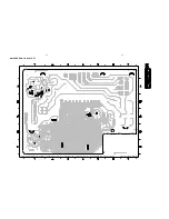
Page 37: ...assembly drawing shows a summary of all possible versions For components used in a specific version see schematic diagram and respective parts list 3139 113 3478 pt3 dd wk0247 8 3 8 3 MAINS BOARD CHIP LAYOUT ...

Page 38: ... 6223 100n 100n 2225 3226 2207 47n BC337 40 7203 470R 3222 1K5 3229 3212 2201 6226 BZX79 C39 BC847B 7205 3211 6221 1N4003 9 Low Power Supply VOLTAGE REGULATION F2 FTD T5AL RES 4K7 3228 3202 3K9 6229 1N4148 1N4148 BC817 40 7202 100K 3227 33K 3233 6227 3221 2K2 6228 1N4148 33K 7200 6202 GBU8D 100n 2204 6204 BZX79 B8V2 3231 100R 3217 47K 2229 47n 470n 2213 0u47 2208 47K 3214 3201 4K7 5 4 6 8 9 7 1 12...

Page 39: ... 23303 33k 1 0 6W 3214 4822 117 12925 47k 1 0 063W 3215 4822 052 10109 10R 5 0 33W 3217 4822 117 12925 47k 1 0 063W 3219 4822 116 52228 680R 5 0 5W 3220 4822 051 30105 1M 5 0 062W 3221 4822 051 30222 2k2 5 0 062W 3222 4822 051 30471 470R 5 0 062W 3223 4822 051 30103 10k 5 0 062W 3224 4822 117 13632 100k 1 0 62W 3225 4822 051 30475 4M7 5 0 062W 3226 4822 051 30331 330R 5 0 062W 3227 4822 117 13632 ...

Page 40: ...CAL PARTS LIST MAINS BOARD TRANSISTORS INTEGRATED CIRCUITS 7204 4822 130 60373 BC857B 7205 5322 130 60159 BC847B 7206 4822 130 60373 BC857B Note Only the parts mentioned in this list are normal service spare parts ...

Page 41: ...and sound control features via the I2C bus I2C_CLK and I2C_DATA lines 2 Line out Line out is taken directly from the Audio Processor IC 7506 Muting is done via transistors 7003 7007 and 7008 3 Pre amplifier IC 7700 NJM4556AM provides pre amplification of the output signals from the Audio Processor IC 7506 Muting of audio signals to PowerAmplifier IC 7301 and 7302 during Headphone application and S...

Page 42: ... diagram and respective parts list 3139 113 3477 pt1 dd wk0217 This assembly drawing shows a summary of all possible versions For components used in a specific version see schematic diagram and respective parts list 3139 113 3477 pt1 dd wk0217 9 2 9 2 REGULATOR BOARD COPPER SIDE VIEW REGULATOR BOARD COMPONENT SIDE VIEW ...

Page 43: ...12 BC547B 7408 1N4148 6401 GND_A VCD_GND 7405 BD438 2K2 3425 7411 BC547B 68R 3415 470R 3411 2402 47u 2403 4u7 10u 2415 15K 3407 7409 BC327 25 10K 3410 6407 BZX79 B4V7 3421 5R6 1K 3412 120R 3417 10K 3418 BC557B 100R 3431 100R 3427 7402 GND_A GND_A 9401 6404 1N4148 22K 3423 VCD_GND 1171 1400 EH B 1 2 2K2 3404 100u 2407 2400 2u2 7404 BC557B 3432 1K2 10u 1K 3414 2405 270R 3405 3433 1K5 BZX79 C15 BC547...

Page 44: ...assembly drawing shows a summary of all possible versions For components used in a specific version see schematic diagram and respective parts list 3139 113 3479 pt2 dd wk0247 9 4 9 4 COMBI BOARD CHIP LAYOUT ...

Page 45: ...embly drawing shows a summary of all possible versions For components used in a specific version see schematic diagram and respective parts list 3139 113 3479 pt2 dd wk0247 9 5 9 5 COMBI BOARD COMPONENT LAYOUT ...

Page 46: ...B 7310 5300 1u 3342 10K 3379 2K2 GND_A 3353 1K8 1 3336 5K6 1307 A YKD21 0026 2 1300 BZX79 B3V9 6307 2324 47p A1 2335 10u A1 6304 BYV28 200 24 GND_A 1N4003 6300 3340 330R 470R 3308 1u 2310 2315 4n7 330R 3304 2305 47u 0300 A1 6315 9261 O2 10 RF 1 STBY 6 VCC 12 3303 330R 7301 AN7591 B1 8 B2 11 GND1 3 GND2 9 IN 5 NF1 4 NF2 2 O1 7 47n 2321 2 3 4 5 6 7 8 9 C1 1301 EH B 1302 1 2319 47n BC856B 7307 2K2 33...

Page 47: ...4 2530 1n 5306 470p 2502 GND_D GND_A GND_A 220n 2513 GND_A GND_A GND_A 2524 33n 3513 5K6 1K 3566 GND_A GND_A 3511 12K 4n7 2510 GND_A 2564 100n 2563 100n 470n 2515 BC847B 7505 GND_A 3808 470R GND_A 3503 15K 3508 8K2 GND_A 33n 2523 5K6 3516 820p 2505 3540 470R 3541 470R 7 8 9 3809 470R 23 24 25 26 27 28 3 4 5 6 14 15 16 17 18 19 2 20 21 22 TDA7468D 7506 1 10 11 12 13 470p 2504 15K 3565 470n 2516 470...

Page 48: ...3709 1015 FE BT VK N 7700 B NJM4556AM 5 6 7 8 4 3105 10K 470R 3095 GND_D 3107 270R 2062 100p 4252 GND_A 3031 10K GND_A 1u 2032 3K3 3096 3097 3K3 2045 100p GND_A 3057 1K 3707 27K GND_A 2070 GND_D 2u2 5700 100n 7015 BC847B 2707 100p 15p 2028 M62320FP 7005 CS0 16 15 CS1 14 CS2 4 D0 D1 5 6 D2 7 2708 0u47 1N4148 6002 10R 3713 GND_A 3062 10K 27K 3705 VCD_ON GND_A 100p 2706 GND_A 27K 3700 GND_A 470p 2702...

Page 49: ...80 1u 3 4 SA_IN 3 4 BC817 25 7011 3073 470R 1K5 3043 15K 3804 GND_D 3021 1K5 10K 3111 3362 6K8 YKC21 3424 4 5 1001 B 3064 2K7 2006 100n EH B 1021 2068 100n 3099 560R 2K2 3039 3051 2K2 470R 1K5 3026 BC857B 7008 5V6 4u7 2011 4K7 3079 1025 FE BT VK N 1 2 3 4 5 6 7 8 9 GND_A 10n 2000 3038 SICL NTC GND_D LOW_PWR_CTRL 6RG 5001 1 2 3 4 1u 2081 1u 2021 2n2 2036 7007 BC847B GND_A 3361 1K 3102 GND_D 12V_A 1...

Page 50: ...0V 2339 2238 586 59812 100nF 50V 2340 2238 586 59812 100nF 50V 2341 2020 012 93664 100uF 20 50V 2501 4822 126 13881 470pF 5 50V 2502 4822 126 13881 470pF 5 50V 2503 4822 126 13881 470pF 5 50V 2504 4822 126 13881 470pF 5 50V 2505 3198 016 38210 820pF 25V 2506 3198 016 38210 820pF 25V 2507 4822 126 13881 470pF 5 50V 2508 4822 126 13881 470pF 5 50V 2509 4822 126 13193 4 7nF 10 63V 2510 4822 126 13193...

Page 51: ... 051 30102 1k 5 0 062W 3362 4822 051 30682 6k8 5 0 062W 3363 4822 051 30102 1k 5 0 062W 3364 4822 051 30333 33k 5 0 062W 3365 4822 051 30684 680k 5 0 062W 3366 4822 050 21003 10k 1 0 6W 3367 4822 051 30683 68k 5 0 062W 3377 4822 117 12925 47k 1 0 063W 3378 4822 051 30102 1k 5 0 062W 3379 4822 051 30222 2k2 5 0 062W 3380 4822 051 30222 2k2 5 0 062W 3503 4822 051 30153 15k 5 0 062W 3505 4822 051 302...

Page 52: ...817 25 7010 5322 130 60159 BC847B 7011 4822 130 42804 BC817 25 7012 4822 130 42804 BC817 25 7013 4822 130 60373 BC857B 7300 5322 130 60159 BC847B 7301 9322 153 02682 AN7591 7302 9322 153 02682 AN7591 7304 4822 130 11578 STP16NE06 7307 4822 130 60373 BC856B 7308 5322 130 60159 BC847B 7309 4822 130 11336 STP16NE06FP 7310 4822 130 60373 BC856B 7313 4822 130 60373 BC857B 7325 5322 130 60159 BC847B 732...

Page 53: ... 1 TABLE OF CONTENTS Pin description 10 2 Blockdiagram 10 3 Component Layout Main Board 10 4 Circuit Diagram 10 5 Exploded View 10 6 Partslist 10 7 Universal Loader Single Disc Tray Loader Layout stage 5 ...

Page 54: ...r PLL is used 25 TEST1 GND test control input 1 this pin should be tied low 26 CL16 CD10 NPC 16 9344 MHz system clock output 27 DATA CD10 NPC serial data output 3 state 28 WCLK CD10 NPC word clock output 3 state 29 SCLK CD10 NPC serial bit clock output 3 state 30 EF CD10 NPC C2 error flag output 3 state 31 TEST2 GND test control input 2 this pin should be tied low 32 KILL CD10 Mute control kill ou...

Page 55: ...1 R2 MOT1 SIGNAL PROCESSOR CD10 SAA7324 SAA7325 TRAY MOTOR SL RA FO DIODES PHOTO D3 D2 D5 D1 D4 INNER SWITCH SW INFO TRAY OUT TRAY IN LASER MONITOR DIODE TURNTABLE MOTOR DISC CD MECHANISM TRAY MAINBOARD 7801 3 3V 7802 LASER CONTROL HF AMPLIFIER TZA1024 TZA1025 42 40 39 5 17 21 52 57 64 1 13 5V 8V 2 8V 16 17 20 4 5 7 V4 61 2 ISLICE 3 63 51 8 7 6 2 5 1 3 11 6 14 6 12 25 31 4 2 1 4 3 2 1 4 3 3 3V SCL...

Page 56: ...1 D3 3842 D3 3843 D3 3844 D3 3845 D3 3846 D3 3847 C3 3848 D3 3849 D3 3850 D3 3851 C4 3856 A4 3857 B5 3858 B5 3862 A6 3863 B5 3864 B5 3865 B5 3866 B5 3867 B5 3868 B6 3869 B5 3870 C6 3871 E2 3872 C6 3873 C6 3874 C6 3875 C6 3876 C6 3877 D6 3878 D5 3879 D2 3880 B5 3881 E2 3882 E2 3883 B4 3884 E3 3885 A4 3886 B4 3887 B4 3889 B4 3890 D1 3891 A4 3892 E1 3894 C5 3895 C4 3896 D1 3907 B5 3908 B5 3909 A4 391...

Page 57: ...13 14 15 16 2 3 4 5 6 1800 15R 3800 3866 3817 10K 220p 2808 3820 4R7 3822 22K 1n5 2842 2809 220p LDON VrefCD10 VrefCD10 VrefCD10 SLI Innersw VrefCD10 FOC TRA TRA FOC HFIN RAB SICL SILD SDA SLI DIS DIS PORE DOBM Innersw Focus search 2V 1s Laser damaged U 400mV 1 5V 1 5V 1 4V 1 5V 1 5V 3 0V 3 2V 3 2V 3 2V 3 2V 3 3V 5 0V 8 0V 10 8V 13 2V 4 1V 4 0V 2 8V 8V 1 5V 1 5V 0V 0 2V 1 5V 1 6V 1 6V 1 9V 1 5V 2 ...

Page 58: ... 3103 304 71820 PULLEY GEARWHEEL 205 3103 304 71830 GEARWHEEL 206 3103 304 71910 DRIVING BELT 207 3103 308 54160 MOTOR ASSY 210 3103 301 06660 SPRING SUPPORT 220 3103 304 71790 SUPPORT CD 222 4822 529 10387 RUBBER DAMPER CD DRIVE FRONT 223 4822 529 10387 RUBBER DAMPER CD DRIVE FRONT 230 3103 308 11940 CLAMPER ASSY DA11 240 3103 309 05350 CD DRIVE MCD1B Exploded view UNIVERSAL LOADER ...

Page 59: ...0V 2872 4822 126 13883 220pF 5 50V 2873 3198 029 12210 220µF 20 10V CAPACITORS 2874 4822 124 21732 10µF 20 25V 2875 4822 124 21732 10µF 20 25V 2876 3198 024 44730 47nF 5 50V 2877 4822 126 14305 100nF 10 16V 2878 4822 126 14305 100nF 10 16V 2879 4822 122 31765 100pF 5 50V 2880 3198 016 31020 1nF 5 25V 2883 4822 126 14043 1µF 20 16V 2884 4822 126 14043 1µF 20 16V RESISTORS 3800 4822 051 20159 15Ω 5 ...

Page 60: ...0805 4820 4822 051 20008 CHIP JUMPER 0805 4821 4822 051 20008 CHIP JUMPER 0805 4822 4822 051 20008 CHIP JUMPER 0805 4823 4822 051 20008 CHIP JUMPER 0805 4824 4822 051 20008 CHIP JUMPER 0805 RESISTORS 4825 4822 051 20008 CHIP JUMPER 0805 4826 4822 051 20008 CHIP JUMPER 0805 4827 4822 051 20008 CHIP JUMPER 0805 4829 4822 051 20008 CHIP JUMPER 0805 4830 4822 051 20008 CHIP JUMPER 0805 4831 4822 051 2...

Page 61: ...Exploded_View_3139 119 35580 dd wk0249 11 1 11 1 SET MECHANICAL EXPLODED VIEW ...

Page 62: ...x4mm 0250 3139 114 78651 Bracket Antenna 0252 3139 114 75290 Bracket Combi 0253 3139 114 76040 Panel Left 21M 22 0253 3139 114 75880 Panel Left V2 37 0254 3139 114 76050 Panel Right 21M 22 0254 3139 114 75890 Panel Right V2 37 0255 3139 114 76030 Cover Top 21M 22 0255 3139 114 75380 Cover Top V2 37 0256 3139 114 76390 Panel Rear 21M 0256 3139 114 76020 Panel Rear 22 0256 3139 114 75370 Panel Rear ...

Reviews: