2-4
2-4
Repair Hints
1) During repair it is possible to disconnect the ECO6 Tuner
Board completely unless the fault is suspected to be in
that area. This will not affect the performance of the rest
of the set.
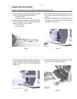
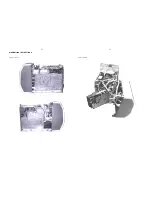
2) Care should be taken not to damage or tear the LCD
Module Cable during repair (see Figure 18 & Figure 19).
The LCD Module Cable may be damage or tear as shown
in Figure 20 if too much force is applied when removing
the Black Tape during repair.
Note: The flex cables are very fragile, care should be taken
not to damage them during repair. After repair, be
very sure that the flex cables are inserted properly
into the flex sockets before encasing, otherwise faults
may occurs.
Dismantling of the Bottom assembly
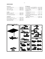
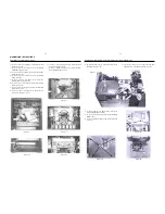
1) Loosen 2 screws T as shown in Figure 16 to remove the
Combi & Regulator boards assembly (pos 1101-1001 &
pos 1101-1003).
2) Loosen 2 screws U as shown in Figure 17 to remove the
Housing Fan Top (pos 267).
Note : During Fan (pos 1110) replacement, care should
be taken to ensure that the following are correct:
- fan blade direction
- fan wire position
Dismantling of the Rear Panel
1) Loosen 3 screws Q and 2 catches C3 (see Figure 15) to
remove the Tuner Board assembly.
2) Loosen 1 screw S (see Figure 15) to free the Mains
Socket Board from the Panel Rear (pos 256).
3) Loosen 5 screws R and 2 catches C4 (see Figure 15) to
remove the Panel Rear (pos 256) by sliding it out towards
the rear.
Figure 15
Figure 16
Figure 17
Figure 18
Figure 19
Figure 20
DISMANTLING INSTRUCTIONS

