10
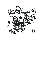
• 1 front stabilizer cover
• 1 rear stabilizer cover
• 1 console
• 2 drink bottle holder
• 2 pedals
• 1 hardware kit
Assembly
Read each step’s instructions and study the drawing carefully to become
familiar with all the parts and procedures before beginning each step.
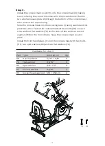
Step 1.
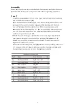
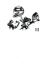
• Install the rear stabilizer (7) onto the main frame (1) with the four bolts
(65) and four flat washers (84).
• Slide the handle bar assembly (6) onto the receiving tubes of the seat
carriage (4). Secure the handle bar assembly starting with the two
bolts (175) install from the inside hole of the receiving tube, and
assemble the two flat washers (77) and two nuts (89). Secure the four
bolts (71) from the top side of the tubes and assemble the four flat
washers (77) and four nuts (89).
• Attach the end of the gas shock to the seat back angle adjustment
bracket and secure with one bolt (118) and two flat washers (115).
Attach the cover (24) located onto the bolt (175) with two nuts (91).
Tighten all hardware securely.
• Connect the left hand pulse wire (27) into the corresponding left socket
(42) located in the left plastic side case under the seat carriage, and
the right hand pulse wire (21) into the right socket (26).
Part
Type
Description
Hardware for step 1
Qty
65
71
77
84
89
91
115
118
175
Hex head bolt
Hex head bolt
Flat washer
Flat washer
Nyloc nut
Nyloc nut
Flat washer
Hex head bolt
Hex head bolt
3/8" × 2-1/4"
3/8" × 2"
Ø3/8"
Ø3/8"
3/8" × 7T
5/16" × 6T
Ø8.5
5/16" × 1-1/4"
3/8" × 2-3/4"
4
4
6
4
6
1
2
1
2

