background image

RFX9600 Manual de inicio

3

Contenido del paquete del Extensor

Pronto Serial Extender

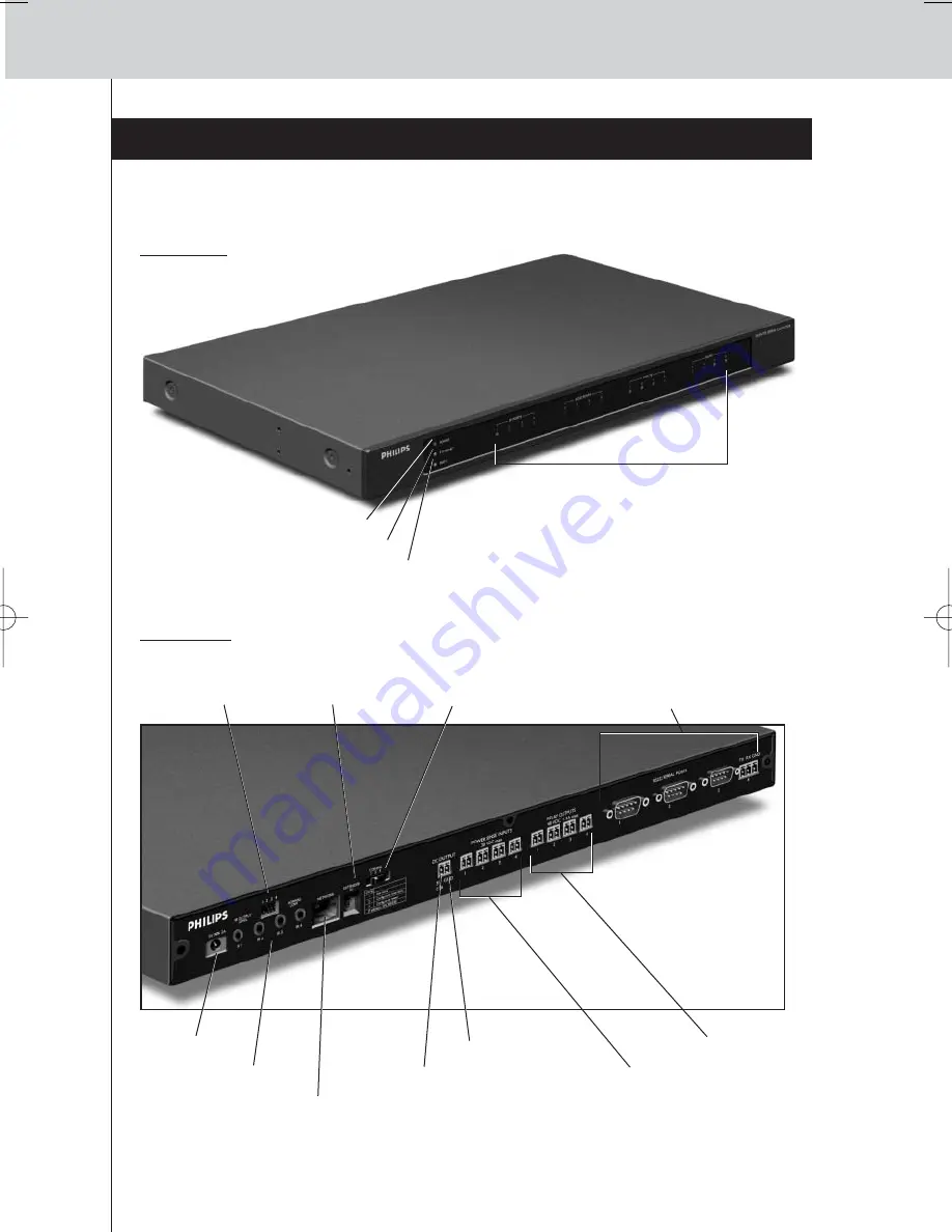
Panel frontal

Interruptor de
Configuración

Entrada de
corriente

4 puertos IR

4 conmutadores DIP
para las salidas IR

Interruptor del
ID del Extensor

Entrada Ethernet (RJ45)

4 entradas de
detección de corriente

4 salidas de relé

Salida de 5 V CC

Toma de tierra

4 puertos RS232 – 
3 conectores DB9 y 
un conector de 3 pines

4 grupos de 4 LED para cada
• Puerto de infrarrojos (IR);
• Puertos serie (RS232);
• Entradas de sensores;
• Salidas de relé.

Indicador LED Power (encendido)

Indicador LED Ethernet

Indicador LED Busy (ocupado)

Panel trasero

RFX9600_SG_ESFv3.qxd  07-09-2006  15:38  Pagina 20

Summary of Contents for Pronto RFX9600

Page 1: ...RFX9600 Starter s Guide Manual de inicio Guide de démarrage FR ES EN ...

Page 2: ......

Page 3: ...ENGLISH RFX9600 Starter s Guide ESPAÑOL FRANÇAIS Starter s Guide Manual de inicio Guide de démarrage RFX9600 ...

Page 4: ...Equipment 7 Connecting to Serial Equipment 7 Connecting to a Lutron RadioRa Lighting System 8 Inserting the Escient Fireball Audio Server in the Network 8 Connecting the Extender to the Network 9 Using the Extender 9 Configuring the Extender 9 Support 11 Troubleshooting 11 What Do the LEDs Indicate 11 Finding the Exact Location of an AV component s IR Receiver 12 Operating AV components with the E...

Page 5: ...allows you to use power sensing for reliable power on off switching You can also use it to control drapes and projector lifts for example In order to use the Extender in a wireless Pronto Network Install the Extender connect it to a router and external equipment like a TV or receiver Configure the Extender connect it to the PC and use the Configuration Tool The Extender is used in a network with a...

Page 6: ...ports 4 dipswitches for the IR outputs Extender ID switch Ethernet input RJ45 4 Power sense inputs 4 Relay outputs 5V DC output Grounding 4 RS232 ports 3 DB9 connectors and one 3 pin connector 4 groups of 4 LEDs each for the IR ports Serial RS232 ports Sensor inputs Relay outputs Power LED Ethernet LED Busy LED Back Panel ...

Page 7: ...the Extender away from heat sources such as amplifiers Mounting Kit 2 Dual IR Emitters 2 Mini jack IR Cables Power Adapter Configuration Cable Crossed Ethernet cable x 2 x 6 x 4 x 4 x 4 Fit the mounting plate on the Extender with the screws Attach the Extender to a rack using the screws washers and nuts ...

Page 8: ... the Extender a Dual IR emitter or a mini jack IR cable Insert the mini jack in the Extender and attach an emitter to the infrared display of the infrared controlled device Insert one mini jack in the Extender and the other in the infrared controlled device Adjusting the Power Level of the IR Outputs At the back of the Extender there are 4 dipswitches one for each IR output Use these dipswitches t...

Page 9: ...e Extender this information is subsequently transmitted to the Extender Some AV components such as receivers have mini jack outputs specifically for this purpose These mini jack outputs can be connected to the power sense inputs on the Extender For video sources video sensor modules can be used Make sure that you create the specific power sensing commands in the action list of ProntoEdit Professio...

Page 10: ...wiring and Phoenix connectors Connecting to Serial Equipment There are two ways to connect serial equipment to the Extender Tip In case you experience communication problems when using the RS232 wiring solution illustrated above make sure that the GND pin on the Extender is grounded correctly on the side of the AV component ...

Page 11: ...tem 5 Open the Lutron Lighting System Properties 6 Adjust the settings of the Lutron Lighting System 1 Select the Extender to which the Lutron Lighting System is connected 2 Select the port on the Extender to which it is connected Inserting the Escient Fireball Audio Server in the Network 1 Connect the Escient to the router 2 Open ProntoEdit Professional 3 Open the configuration file 4 Insert the ...

Page 12: ...on switch to 1 for use 4 Plug in the Extender s power adapter The Extender will start up After startup the Power and Ethernet LEDs are green The Busy LED blinks green when it s processing a code or a macro Configuring the Extender You can connect the Extender directly to the PC for configuration If the Extender is already installed and connected to external equipment it is also possible to configu...

Page 13: ...netmask at hand and follow the onscreen instructions 7 When the configuration is completed disconnect the Extender from the computer and reconnect it to the router with a straight Ethernet cable Set the Configuration switch to 1 for use Configuration through a router 1 The Extender is already connected to the router Connect the router to the PC as well 2 Set the Configuration switch to 3 for confi...

Page 14: ...ender is in configuration Refer to the topic There is an IP conflict on page 11 Red Refer to the topic There are duplicate Extender IDs on page 12 Refer to the Refer to the topic The IP address cannot be determined on page 11 Red blinking The Extender is starting up Wait until startup has finished There is an IP conflict There is another AV component in the network that is using the same fixed IP ...

Page 15: ...is configured correctly in the Configuration Tool and connected properly to the AV components Make sure that the switches on the Extender are set correctly There are duplicate Extender IDs Using the Extender ID switch assign a unique ID to each Extender in the same Pronto Network Make sure the Control Panel is configured accordingly in ProntoEdit Professional You can use up to 16 different Extende...

Page 16: ...and connected to equipment it may be more convenient to update it through the router 1 The Extender is already connected to the router Connect the router to the PC as well 2 Set the Configuration switch to 3 for configuration The Extender will restart After start up the Power and Ethernet LEDs are green and the Busy LED is red green blinking 3 Open ProntoEdit Professional on the PC 4 In the Tools ...

Page 17: ...addressable outputs for IR emitters Ethernet RJ45 connection 4 RS232 ports for control 4 power sense inputs 4 30 VDC or 4 30 VAC rms 4 Relay outputs 48 VDC or 48 VAC rms 2 A max power 60 W Voltage output for general use 5 VDC 0 3 A Settings Extender ID 16 positions IR power output 2 levels normal low Configuration Use mode configure with cross cable or via router LED indications 3 LEDs for Power E...

Page 18: ...quipo en serie 7 Conexión al Sistema de Iluminación Lutron RadioRa Lighting System 8 Cómo insertar en la red el Servidor de Audio Escient Fireball Audio Server 8 Conexión del Extensor a la red 9 Uso del Extensor 9 Configuración del Extensor 9 Soporte 11 Resolución de problemas 11 Qué significan los indicadores LED 11 Cómo encontrar la ubicación exacta del receptor IR de un componente AV 12 Funcion...

Page 19: ...nmutación de alimentación segura También puede utilizarlo para controlar elevadores de proyectores y pantallas por ejemplo Para utilizar el Extensor en una red Pronto Network inalámbrica Instale el Extensor conéctelo al router y al equipo externo como un televisor o un receptor Configure el Extensor conéctelo al PC y utilice la herramienta de configuración Configuration Tool El Extensor se utiliza...

Page 20: ...Interruptor del ID del Extensor Entrada Ethernet RJ45 4 entradas de detección de corriente 4 salidas de relé Salida de 5 V CC Toma de tierra 4 puertos RS232 3 conectores DB9 y un conector de 3 pines 4 grupos de 4 LED para cada Puerto de infrarrojos IR Puertos serie RS232 Entradas de sensores Salidas de relé Indicador LED Power encendido Indicador LED Ethernet Indicador LED Busy ocupado Panel trase...

Page 21: ...de calor como por ejemplo amplificadores Kit de montaje 2 emisores IR duales 2 cables con conectores mini jack Adaptador de corriente Cable de configuración Cable Ethernet cruzado x 2 x 6 x 4 x 4 x 4 Fije la placa de montaje en el Extensor con los tornillos Acople el Extensor a los estantes utilizando los tornillos las arandelas y las tuercas ...

Page 22: ...ual o un cable IR con conectores mini jack Inserte el mini jack en el Extensor y acople un emisor a la pantalla de infrarrojos del dispositivo controlado mediante infrarrojos Inserte un mini jack en el Extensor y el otro en el dispositivo controlado mediante infrarrojos Ajuste del nivel de corriente de las salidas IR En la parte trasera del Extensor hay 4 conmutadores DIP uno para cada salida IR U...

Page 23: ...posteriormente al Extensor Algunos componentes AV como los receptores tienen salidas de miniconectores específicas para esto Estas salidas para miniconectores pueden conectarse a las entradas de detección de corriente en el Extensor Para fuentes de vídeo pueden utilizarse los módulos de sensores de vídeo Asegúrese de haber utilizado los comandos específicos de detección de corriente en la lista de...

Page 24: ... conectores Phoenix Conexión a un equipo en serie Hay dos maneras de conectar equipos en serie al Extensor Consejo práctico En el caso de que experimente problemas de comunicación al utilizar la solución de cableado RS232 indicada anteriormente asegúrese de que el pin GND del Extensor esté conectado a tierra de forma correcta en el lado del componente AV ...

Page 25: ...bra Lutron Lighting System Properties 6 Ajuste la configuración del sistema de iluminación Lutron 1 Seleccione el Extensor al que debe conectarse el sistema de iluminación Lutron 2 Seleccione el puerto del Extensor al que está conectado Cómo insertar en la red el servidor de música Escient Fireball Audio Server 1 Conecte el servidor de música Escient al router 2 Abra ProntoEdit Professional 3 Abra...

Page 26: ...ción 1 para su uso 4 Conecte el adaptador de corriente del Extensor El Extensor arrancará Después de arrancar los indicadores LED Power y Ethernet estarán iluminados en verde El indicador LED Busy parpadeará en verde si está procesando un código o una macro Configuración del Extensor Puede conectar el Extensor directamente al PC para su configuración Si el Extensor ya está instalado y conectado a ...

Page 27: ... la máscara de red y siga las instrucciones que aparezcan en pantalla 7 Una vez completada la configuración desconecte el Extensor del ordenador y vuelva a conectarlo al router con un cable Ethernet directo Ajuste el Interruptor de Configuración a la posición 1 para su uso Configuración a través de un router 1 El Extensor ya está conectado al router Conecte también el router al PC 2 Ajuste el Inte...

Page 28: ...trol Panel Parpadeo rojo verde El Extensor se encuentra en modo de configuración Consulte el tema Hay un conflicto de IP en la página 11 Rojo Consulte el tema Hay ID del Extensor duplicados en la página 12 Consulte el tema La dirección IP no puede determinarse en la página 11 Parpadeo rojo El Extensor está arrancando Espere hasta que termine de arrancar Hay un conflicto de IP Hay otro componente A...

Page 29: ...e el Control Panel está configurado correctamente en ProntoEdit Professional Asegúrese de que el Extensor está configurado correctamente en la herramienta Configuration Tool y que está conectado correctamente a los componentes AV Asegúrese de que los interruptores del Extensor están ajustados correctamente Hay ID del Extensor duplicados Utilizando el interruptor del ID del Extensor asigne un ID ún...

Page 30: ...zación de firmware 7 Siga las instrucciones que aparecen en pantalla Actualización del Extensor a través de un router Si el Extensor ya está instalado y conectado a un equipo es posible que sea mas cómodo actualizarlo a través del router 1 El Extensor ya está conectado al router Conecte también el router al PC 2 Ajuste el Interruptor de Configuración a la posición 3 para su configuración El Extens...

Page 31: ... 4 entradas de detección de corriente 4 30 V CC o 4 30 V CA rms 4 salidas de relés 48 V CC o 48 V CA rms 2 A potencia máx 60 W Salida de tensión para uso general 5 V CC 0 3 A Configuración ID del Extensor 16 posiciones Salida de corriente IR 2 niveles normal bajo Configuración modo de uso configurar con cable cruzado o mediante router Indicadores LED 3 indicadores LED para alimentación Power red E...

Page 32: ...r relais 7 Connexion à un équipement en série 7 Connexion à un Lutron RadioRa Lighting System 8 Insertion du Escient Fireball Audio Server dans le réseau 8 Connexion du Prolongateur au réseau 9 Utilisation du Prolongateur 9 Configuration du Prolongateur 9 Support 11 Dépannage 11 Qu indiquent les voyants 11 Recherche de l emplacement exact du récepteur IR d un composant audio vidéo 12 Fonctionnemen...

Page 33: ...our vous assurer de toujours ouvrir couper l alimentation en courant correctement De plus vous pouvez l utiliser pour commander les écrans de projection et les potences de projecteur par exemple Pour utiliser le Prolongateur dans un réseau Pronto sans fil Installez le Prolongateur connectez le à un routeur et à l équipement externe tel qu un téléviseur ou un récepteur Configurez le Prolongateur co...

Page 34: ... Entrée du courant 4 ports IR 4 commutateurs DIP pour les sorties infrarouges Commutateur d ID de Prolongateur Entrée Ethernet RJ45 4 entrées de détection de l alimentation 4 sorties de relais Sortie 5V CC Mise à la terre 4 ports RS232 3 connecteurs DB9 et un connecteur à 3 broches 4 groupes de 4 voyants pour les ports IR les ports sériels RS232 les entrées de capteur les sorties de relais ...

Page 35: ...ur de toute source de chaleur telle que les amplificateurs Kit de montage 2 émetteurs IR doubles 2 câbles à mini prise IR Adaptateur secteur Câble de configuration Câble Ethernet croisé x 2 x 6 x 4 x 4 x 4 Fixez la plaque de montage sur le Prolongateur à l aide de vis Fixez le Prolongateur à un rack au moyen de vis de rondelles et d écrous ...

Page 36: ...Prolongateur un émetteur IR double ou un câble IR avec mini prise Insérez la mini prise dans le Prolongateur et fixez un émetteur à l écran infrarouge de l appareil commandé par infrarouges Insérez une mini prise dans le Prolongateur et l autre dans l appareil commandé par infrarouges Réglage de la puissance des sorties IR Au dos du Prolongateur vous trouverez 4 commutateurs DIP un pour chaque sor...

Page 37: ...rmations sont transmises au Prolongateur Certains composants audio vidéo tels que les récepteurs possèdent des sorties à mini prise spécifiquement à cet effet Ces sorties à mini prise peuvent être connectées aux entrées de détection de l alimentation sur le Prolongateur Pour les sources vidéo vous pouvez utiliser des modules de détection vidéo Veillez à créer les commandes spécifiques de détection...

Page 38: ...nnecteurs Phoenix Connexion à un équipement en série Il existe deux façons de connecter un équipement en série au Prolongateur Astuce Si vous rencontrez des problèmes de communication lors de la solution de câblage comportant le RS232 illustrée ci dessus assurez vous que la broche GND sur le prolongateur est mise correctement à la terre du côté du composant audio vidéo ...

Page 39: ...tem 5 Ouvrez Lutron Lighting System Properties 6 Paramétrez les options du Lutron Lighting System 1 Sélectionnez le Prolongateur auquel le Lutron Lighting System est connecté 2 Sélectionnez le port du Prolongateur auquel le Lutron Lighting System est connecté Insertion de l Escient Fireball Audio Server dans le réseau 1 Connectez l Escient au routeur 2 Ouvrez ProntoEdit Professional 3 Ouvrez le fi...

Page 40: ...ur de configuration sur 1 pour utiliser le Prolongateur 4 Branchez l adaptateur secteur du Prolongateur Le Prolongateur démarre Après le démarrage les voyants Power alimentation et Ethernet sont verts Le voyant Busy occupé clignote en vert lorsqu il traite un code ou une macro Configuration du Prolongateur Vous pouvez connecter le Prolongateur directement au PC afin de le configurer Si le Prolonga...

Page 41: ...e réseau et suivez les instructions qui apparaissent à l écran 7 Lorsque la configuration est terminée déconnectez le Prolongateur de l ordinateur et reconnectez le au routeur au moyen d un câble Ethernet droit Placez le commutateur de configuration sur 1 en vue de l utilisation Configuration par un routeur 1 Le Prolongateur est déjà connecté au routeur Connectez également le routeur au PC 2 Place...

Page 42: ...t Le Prolongateur est en cours de configuration Reportez vous à la rubrique Il existe un conflit IP de la page 11 Rouge Reportez vous à la rubrique Il existe des ID de prolongateur dupliqués de la page 12 Reportez vous à la rubrique Impossible de déterminer l adresse IP de la page 11 Rouge clignotant Le Prolongateur démarre Attendez jusqu à la fin du démarrage Il existe un conflit IP Un autre comp...

Page 43: ...ue le Control Panel est correctement configuré dans le ProntoEdit Professional Vérifiez que le Prolongateur est correctement configuré dans le Configuration Tool et correctement connecté aux composants audio vidéo Vérifiez que les commutateurs du Prolongateur sont correctement paramétrés Il existe des ID de prolongateur dupliqués Si vous utilisez le commutateur d ID de Prolongateur affectez un ID ...

Page 44: ... du micrologiciel s ouvre 7 Suivez les instructions à l écran Mise à jour du prolongateur par un routeur Si le prolongateur est installé et connecté à l équipement il peut s avérer plus pratique de le mettre à jour par un routeur 1 Le Prolongateur est déjà connecté au routeur Connectez également le routeur au PC 2 Placez le commutateur de configuration sur 3 en vue de la configuration Le Prolongat...

Page 45: ...pour émetteurs IR Connexion Ethernet RJ45 4 ports RS232 pour commande 4 entrées de détection de l alimentation 4 30 VCC ou 4 30 VCA rms 4 sorties de relais 48 VCC ou 48 VCA rms 2 A puissance max 60 W Puissance de sortie pour utilisation générale 5 VCC 0 3 A Paramètres ID de Prolongateur 16 positions Puissance de sortie IR 2 niveaux normal faible Configuration mode d utilisation configuration avec ...

Page 46: ...ntee that interference will not occur in a particular installation If the equipment does cause harmful interference to radio or television reception which can be determined by turning the equipment off and on the user is encouraged to try to correct the interference by one or more of the following measures Reorient or relocate the receiving antenna Increase the separation between the equipment and...

Page 47: ...lization of this Starter s Guide Concepto y elaboración de este Manual de inicio Documentation et élaboration de ce Guide de démarrage The Human Interface Group De Regenboog 11 2800 Mechelen Belgium http www higroup com 3104 205 3435 1 ...

Page 48: ......

Reviews: