SAP
Second Audio Program
SCL
Serial Clock
SDA
Serial Data
SDAM
Service Default Alignment Mode
SVHS
Super Video Home System
THD
Total Harmonic Distortion
Top Level Menu
This refers to the main menu (as opposed to sub menus) in SAM
V-Chip
Violence-Chip
VCR
Video Cassette Recorder
Y/C
Luminance/Chrominance (video)
Safety Instructions - Resolder Notice
1
Safety regulations require that during a repair:
•
the set should be connected to the mains via an isolating transformer
•
safety components, indicated by the symbol:
should be replaced by components identical to the original ones
•
when replacing the CRT, safety goggles must be worn
2
Safety regulations require that after a repair the set must be returned in its original condition. In
particular, attention should be paid to the following points:
Note:
This resoldering is advised to prevent bad connections due to metal fatigue in solder joints, and
is therefore only necessary for television sets older than 2 years.
•
As a strict precaution, we advise you to resolder the solder joints through which the horizontal
deflection current is flowing, in particular:
-
All pins of the line output transformer (LOT)
-
flyback capacitor(s)
-
S-correction capacitor(s)
-
line output transistor
-
pins of the connector with wires to the deflection coil
-
other components through which the deflection current flows
•
Resolder points are marked by a white circle on the bottom of the CBA.
•
The wire trees and EHT cable should be routed correctly and fixed with the mounted cable
clamps.
•
The insulation of the mains lead should be checked for external damage.
•
The mains lead strain relief should be checked for its function in order to avoid touching the
CRT, hot components or heat sinks.
•
The electrical DC resistance between the mains plug and the secondary side should be checked
(only for sets which have a mains isolated power supply).
This check can be done as follows:
-
unplug the mains cord and connect a wire between the two pins of the mains plug
-
set the mains switch to the on position (keep the mains cord unplugged!)
-
measure the resistance value between the pins of the mains plug and the metal shielding of
the tuner or the aerial connection on the set. The reading should be between 4.5 Megohm and
12 Megohm.
-
switch off the TV and remove the wire between the two pins of the mains plug
•
The cabinet should be checked for defects to avoid touching of any inner parts by the customer.
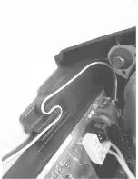
AC Cord Lead Dress
Summary of Contents for PR1906C121
Page 3: ...MAIN CABINET EXPLODED VIEW Page 1 of 1 ...
Page 5: ......
Page 6: ......
Page 7: ......
Page 8: ......
Page 9: ......
Page 10: ......
Page 11: ......
Page 12: ......
Page 13: ......
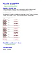
Page 21: ...Display Feature Chart ...
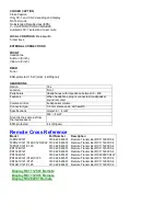
Page 22: ...Display RC1112501 Remote ...
Page 23: ...Display RC1112901 Remote ...
Page 24: ...Display RC282901 Remote ...
Page 25: ...Display Jack Panel Information Chart ...
Page 26: ......
Page 27: ......
Page 41: ...Fig 9a Fig 9b Fig 9c Fig 10a Fig 10b Fig 10c Figures 11 12 Yoke Tilt ...
Page 42: ...Figure 11 Figure 12 ...
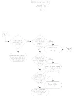
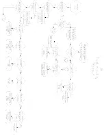
Page 43: ...Display Figure 1 SDAM Flow Chart ...
Page 45: ......

