


1-9
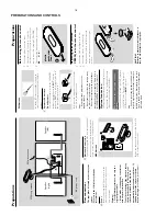
PREPARATIONS AND CONTROLS
)
1
3 4
6
7
8
9
5
!
0
2
^ (
1
!
7
0
8
*
%
@
3
#
$
&
5
Contr
ols
Contr
ols on the system and
remote contr
ol
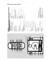
1
ST
ANDBY
-ON/ ECO PO
WER (
B
)
–
switches the system on or to Eco P
ow
er
standb
y/nor
mal standb
y with clock display
.
2
Displa
y screen
–
sho
ws the status of the system.
3
OPEN • CLOSE
√
/
–
opens/closes the CD door
.
4
IR
–
remote sensor
5
V
OLUME (
3
/
4
) (
+
/
-
)
–
adjusts the v
olume lev
el.
–
adjusts the hour
s and min
utes f
or the clock/timer
function.
6
CD Door
7
Mode Selection
ALB
UM/ TUNE/ALB
UM
-
/
+
(
5
/
6
)
for
TUNER
........
tunes to a station
for CD/MP3-CD
fast searches back and
forward within a tr
ack/disc (press
and hold).
for MP3-CD
.....
skips to the beginning of a
cur
rent/previous/subsequent
album.
9
.............................
stops disc pla
yback or er
ases a
disc progr
amme
.
2 ;
...................
star
ts or inter
rupts pla
yback.
PRESET (
J
/
K
)
for
TUNER
........
selects a preset r
adio station.
for CD/MP3 -CD
skips to the beginning of a
cur
rent/previous/subsequent
tr
ack
8
DBB
(Dynamic Bass Boost)
–
enhances the bass.
9
BAND
–
selects a wa
veband.
0
PR
OGRAM
for CD/MP3-CD
progr
ammes tr
acks and
reviews the progr
amme
.
for
TUNER
........
progr
ammes tuner stations.
!
SOURCE
–
selects the respectiv
e sound source f
or CD/
TUNER/ A
UX.
Notes for r
emote contr
ol:
–
Fir
st select the source you wish to
contr
ol b
y
pr
essing one of the source select
ke
ys on the r
emote contr
ol (for e
xample
CD
, TUNER).
–
Then select the desired function (for
e
xample
2 ;
,
J
,
K
).
@
DISPLA
Y/CLOCK
–
sets the clock function.
–
displa
ys disc inf
or
mation dur
ing pla
yback.
#
TIMER
–
activates/ deactivates or sets the timer function.
$
SLEEP
–
activates/deactivates or selects the sleeper time
.
%
DSC
(Digital Sound Contr
ol)
–
selects sound char
acter
istics:
ROCK/
JAZZ/
POP/ CLASSIC
.
^
RDS
–f
or tuner
, displa
ys RDS inf
or
mation.
&
MUTE
–
inter
rupts and resumes sound reproduction.
*
REPEA
T
–
repeats a track/disc progr
amme/entire disc
.
(
SHUFFLE
–
pla
ys disc tr
acks in r
andom order
.
)
n
–c
onnects headphones
Summary of Contents for MCM240
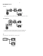
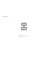
Page 13: ...4 1 4 1 SET BLOCK DIAGRAM ...
Page 14: ...5 1 5 1 SET WIRING DIAGRAM ...
Page 16: ...6 2 6 2 CIRCUIT DIAGRAM ...
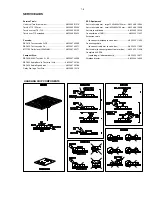
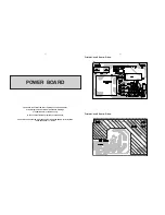
Page 18: ...LAYOUT DIAGRAM KEY BOARD TOP SIDE LAYOUT DIAGRAM KEY BOARD BOTTOM SIDE 7 2 7 2 ...
Page 19: ...7 3 7 3 CIRCUIT DIAGRAM ...
Page 22: ...BLOCK DIAGRAM MICROCONTROLLER UNIT TMP87PP23F 8 3 8 3 ...
Page 23: ...LAYOUT DIAGRAM MAIN BOARD TOP SIDE 8 4 8 4 ...
Page 24: ...8 5 8 5 LAYOUT DIAGRAM MAIN BOARD BOTTOM SIDE ...
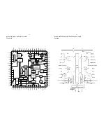
Page 25: ...CIRCUIT DIAGRAM MAIN BOARD MCU PART 8 6 8 6 ...
Page 26: ...CIRCUIT DIAGRAM MAIN BOARD CD PART 8 7 8 7 ...
Page 27: ...CIRCUIT DIAGRAM MAIN BOARD MP3 PART 8 8 8 8 ...
Page 28: ...CIRCUIT DIAGRAM MAIN BOARD AMP PART 8 9 8 9 ...
Page 29: ...CIRCUIT DIAGRAM MAIN BOARD TUNER PART 8 10 8 10 ...