TROUBLESHOOTING
Impor
tant notes f
or users in the
U
.K.
Mains plug
This appar
atus is f
itted with an appro
ved 13
Amp plug.
T
o
change a fuse in this type of plug
proceed as f
ollo
ws:
1
Remo
ve
fuse co
ver and fuse
.
2
Fix new fuse which should be a BS1362 3
Amp
,
A.S.T
.A.
or BSI appro
ved type
.
3
Ref
it the fuse co
ve
r.
If the f
itted plug is not suitab
le f
or y
our sock
et
outlets,
it should be cut off and an appropr
iate
plug f
itted in its place
.
If the mains plug contains a fuse
, this should
ha
ve
a value of 3
Amp.
If a plug without a fuse
is used,
the fuse at the distr
ib
ution board
should not be greater than 3
Amp
.
Note:
The sever
ed plug m
ust be disposed of to
avoid a possible shoc
k hazard should it be
inser
ted into a 13
Amp soc
ket else
wher
e
.
Ho
w to connect a plug
The wires in the mains lead are coloured with
the f
ollo
wing code:
b
lue = neutr
al (N),
bro
wn = liv
e (L).
∂
As these colour
s may not cor
respond with the
colour mar
kings identifying the ter
minals in
your plug,
proceed as f
ollo
ws:
–
Connect the blue wire to the ter
minal
mar
ked N or coloured b
lack.
–
Connect the bro
wn wire to the ter
minal
mar
ked L or coloured red.
–
Do not connect either wire to the ear
th
terminal in the plug,
mar
ked E (or
e
) or
coloured green (or green and y
ello
w).
Bef
ore replacing the plug co
ve
r, mak
e cer
tain
that the cord gr
ip is clamped o
ver the sheath
of the lead - not simpl
y o
ver the tw
o wires.
Cop
yright in the U.K.
Recording and pla
yback of material may
require consent.
See Cop
yr
ight
Act 1956 and
The P
erf
or
mer’
s Protection
Acts 1958 to 1972.
Norge
Typeskilt f
innes på appar
atens under
side
.
Obser
ve
r:
Nettbr
yter
en er sekunder
t
innk
oplet.
Den inneb
ygde netdelen er
derfor ikke fr
ak
oplet nettet så lenge
appar
atet er tilsluttet nettkontakten.
For å redusere faren for br
ann eller elektr
isk
støt,
skal appar
atet ikk
e utsettes f
or regn eller
fuktighet.
Italia
DICHIARAZIONE DI CONFORMIT
A’
Si dichiar
a che l’apparecchio
MCM240 Philips
risponde alle prescr
izioni dell’ar
t. 2 comma 1
del D
.M.
28
Agosto 1995 n.
548.
Fatto a Eindho
ve
n
Philips Consumer Electronics
Philips, Glaslaan 2
5616 JB Eindho
ven,
The Nether
lands
CA
UTION
Use of contr
ols or adjustments or
performance of pr
ocedures other than
her
ein may result in hazardous
radiation e
xposur
e or other unsafe
oper
ation.
VA
R
OITUS
Muiden kuin tässä esitettyjen
toimintojen säädön tai asetusten
m
uutto saattaa altistaa v
aar
alliselle
säteilylle tai m
uille v
aarallisille
toiminnoille
.
Tr
oub
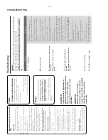
leshooting
W
ARNING
Under no circumstances should you tr
y to repair the system your
self,
as this will in
validate the
w
arr
anty
. Do not open the system as ther
e is a risk of electric shock.
If a f
ault occur
s,
fir
st check the points listed belo
w befor
e taking the system for repair
.
If you
ar
e unable to r
emedy a pr
oblem b
y
follo
wing these hints
,
consult your dealer or Philips for
help.
“
NO DISC
” is displa
y
ed.
Radio r
eception is poor
.
The system does not r
eact when buttons
ar
e pr
essed.
Sound cannot be hear
d or is of poor
quality
.
The left and right sound outputs ar
e
re
versed.
The r
emote contr
ol does not function
pr
operl
y.
The timer is not w
orking.
The Clock/Timer setting is erased.
Inser
t a disc
.
Check if the disc is inser
ted upside down.
W
ait until the moisture condensation at the lens
has cleared.
Replace or clean the disc
, see “Maintenance”.
Use a f
inalised CD-R
W or a cor
rect MP3-CD
for
mat disc
.
If the signal is too w
eak,
adjust the antenna or
connect an exter
nal antenna for better
reception.
Increase the distance betw
een the Micro HiFi
System and y
our
TV or
VCR.
Remo
ve
and reconnect the
AC
po
w
er plug and
switch on the system again.
Adjust the v
olume
.
Disconnect the headphones.
Check that the speaker
s are connected cor
rectl
y.
Check if the str
ipped speak
er wire is clamped.
Mak
e sure the MP3-CD was recorded within
32~256 kbps bit r
ate with sampling frequencies
at 48 kHz, 44.1 kHz or 32 kHz.
Check the speaker connections and location.
Select the source (CD or
TUNER,
f
or example)
bef
ore pressing the function b
utton (
2;
,
¡
,
™
).
Reduce the distance betw
een the remote
control and the system.
Inser
t the batter
y with its polar
ities
(+/– signs) aligned as indicated.
Replace the batter
y.
Point the remote control directl
y to
ward
IR sensor on the front of the system.
Set the clock cor
rectl
y.
Press
TIMER to switch on the timer
.
Po
w
er has been inter
rupted or the po
w
er cord
has been disconnected.
Reset the clock/timer
.
Pr
ob
lem
S
olution
1-10
Summary of Contents for MCM240
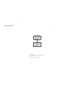
Page 13: ...4 1 4 1 SET BLOCK DIAGRAM ...
Page 14: ...5 1 5 1 SET WIRING DIAGRAM ...
Page 16: ...6 2 6 2 CIRCUIT DIAGRAM ...
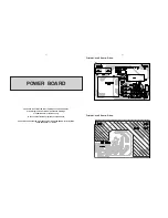
Page 18: ...LAYOUT DIAGRAM KEY BOARD TOP SIDE LAYOUT DIAGRAM KEY BOARD BOTTOM SIDE 7 2 7 2 ...
Page 19: ...7 3 7 3 CIRCUIT DIAGRAM ...
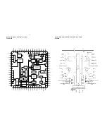
Page 22: ...BLOCK DIAGRAM MICROCONTROLLER UNIT TMP87PP23F 8 3 8 3 ...
Page 23: ...LAYOUT DIAGRAM MAIN BOARD TOP SIDE 8 4 8 4 ...
Page 24: ...8 5 8 5 LAYOUT DIAGRAM MAIN BOARD BOTTOM SIDE ...
Page 25: ...CIRCUIT DIAGRAM MAIN BOARD MCU PART 8 6 8 6 ...
Page 26: ...CIRCUIT DIAGRAM MAIN BOARD CD PART 8 7 8 7 ...
Page 27: ...CIRCUIT DIAGRAM MAIN BOARD MP3 PART 8 8 8 8 ...
Page 28: ...CIRCUIT DIAGRAM MAIN BOARD AMP PART 8 9 8 9 ...
Page 29: ...CIRCUIT DIAGRAM MAIN BOARD TUNER PART 8 10 8 10 ...


