Mechanical Instructions
EN 13
LC7.2E LA
4.
4.3.5
Speakers
This depends on the model/screen size: for the 26” and 32”
models, the bare speakers are accessible, while for the larger
models they are encased, and therefore must be replaced as
assembly when defective.
Full- or Mid-range Speakers (for 26” and 32” models)
1.
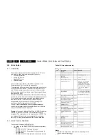
Refer to next figure.
2.
Unplug connectors [1].
3.
Remove screws [2].
Figure 4-14 Mid-range speakers
Tweeters (only for 32” models)
1.
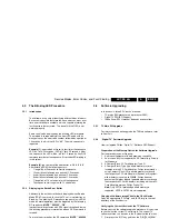
Refer to next figure.
2.
Unplug connectors [1].
3.
Remove screws [2].
Figure 4-15 Tweeters
Speaker box (for 37” and 42” models)
1.
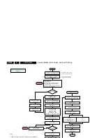
Refer to next figure.
2.
Unplug connectors [1].
3.
Remove screws [2].
When defective, replace the whole unit.
Figure 4-16 Tweeters
4.3.6
1080p Panel
1.
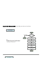
Refer to next figure(s).
2.
Unplug cables [a]. Be careful with the LVDS connectors as
they are very fragile.
3.
Remove the fixation screws [b].
4.
Take the board out (it hinges at the lower side).
5.
Remove the screws [c] that fixate the top and bottom
shieldings, and remove the shieldings.
Note:
Pay special attention not to damage the EMC foams.
Ensure that EMC foams are mounted correctly, especially
notice the large EMC foam “block” [d] at the bottom shielding.
Figure 4-17 1080p panel
Figure 4-18 Bottom shielding 1080p panel
G_16850_010.eps
110107
2
1
2
G_16850_011.eps
110107
2
1
H_16851_011.eps
080307
1
2
2
G_16860_089.eps
150307
b
c
a
c
b
c
c
G_16860_088.eps
150307
d


