DD
C Instructions
2
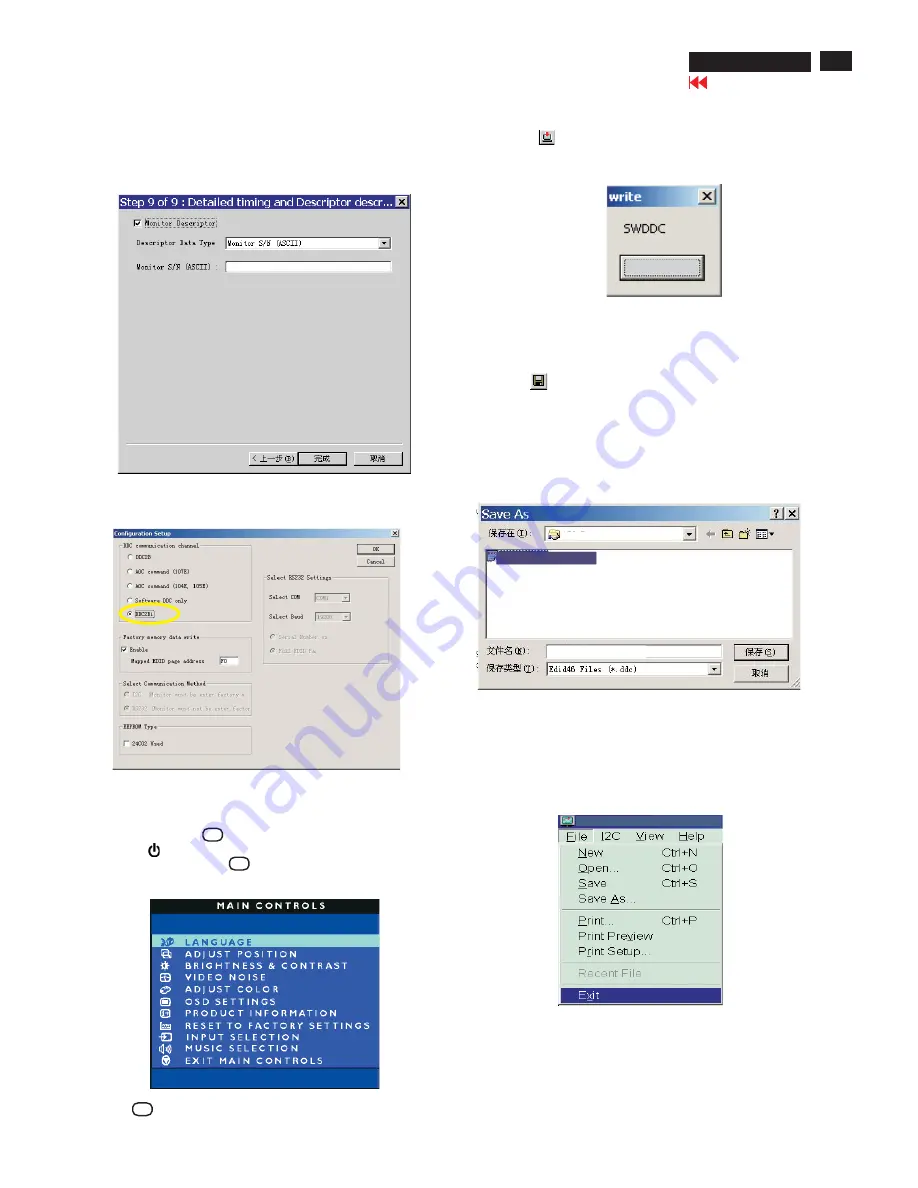
. Access Factory
M
ode
2)
.
[
Push "AU
T
O "
&
" OK " buttons at the same time and hold it
]
+
[
Press power "
" button untill comes out "Windows screen"
] =
> then
release all button, then press OK button, wait until the OS
D
menu with
C
haracters HU
D
SO
N4 170X5 V5
3 2
0040
6
04
(below OS
D
menu) come on
the Screen of the monitor (see Fig. 2
4
).
1)
.
T
urn off monitor.
4
).
C
lic
k
(Write
ED
I
D
) icon from the tool bar to write
DDC
data.
Bring up "ready" a progressing bar on the left, then bring up the
Window as shown in Fig.2
5
, clic
k
the " enter" button to finish Writing
Fig.2
5
ENTER
Fig. 2
4
3) Push OK to e
x
it OS
D
menu.
Fig. 22
8.
C
lic
k
, bring up Fig. 22.
Next
-
C
lic
k
Finish to e
x
it the Step window.
- Serial number can be filled up at this moment (for e
x
ample,
1
23
45
6).
NO
T
E: You must modify the Serial NO. In step 9, otherwise the Serial
NO. In OS
D
Couldn't be modified correctly.
Step
5
: Write
DD
C data
1
.
C
onfiguration should be as Fig. 23. And press OK.
Fig. 23
2.
C
lic
k
.
Save
Step
7
: Exit
DD
C program
Pull down the File menu and select
Ex
it as shown in Fig. 2
7
.
Step
6
: Save
DD
C data
Sometimes, you may need to save
DDC
data as a te
x
t file
for using in other I
C
chip.
T
o save
DDC
data, follow the
steps below:
1
.
C
lic
k
(Save) icon (or clic
k
"file"-> "save as") from the
tool bar and give a file name as shown in Fig. 26.
T
he file type is
ED
I
D4
6 file (
*
.ddc) which can be open in
WordPad. By using WordPad, the te
x
ts of
DDC
data
&
table
(
1
28 bytes, he
x
code) can be modified. If
DDC TEXT
S
&
H
EX T
able ar completely correct, it can be saved as .ddc flie
to re-load it into
DDC
I
C
for
DDC D
ata application.
Fig. 2
7
Step 8:
T
urn off the monitor, e
x
it the factory mode.
Fig. 26
HU
D
SO
N4 170X5 V5
3 2
0040
6
04
HU
D
SO
N4 170X5 V5
3 2
0040
6
04
Factory Mode
Indicator
=====
>
170X5
170X5DDC
Analog
170X5DDC
Analog
Go to cover page
170X5
LC
D
8
1
1
23
45
6
Summary of Contents for hudson iv 170x5
Page 10: ...10 Go to cover page On Screen Display 170X5 LCD Analog signal input ...
Page 18: ...18 Go to cover page Repair Flow Chart 170X5 LCD ...
Page 23: ...23 170X5 LCD Go to cover page Wiring Diagram ...
Page 25: ...25 Go to cover page Scaler Schematic Diagram 1 170X5 LCD ...
Page 26: ...26 Go to cover page Scaler Schematic Diagram 2 170X5 LCD ...
Page 27: ...27 Go to cover page Scaler Schematic Diagram 3 170X5 LCD ...
Page 28: ...28 Go to cover page Scaler Schematic Diagram 4 170X5 LCD ...
Page 29: ...29 Go to cover page 170X5 LCD Scaler Schematic Diagram 5 ...
Page 30: ...30 Go to cover page 170X5 LCD Scaler Schematic Diagram 6 ...
Page 31: ...31 Go to cover page 170X5 LCD Scaler Board C B A 1 ...
Page 32: ...32 Go to cover page 170X5 LCD Scaler Board C B A 2 ...
Page 33: ...33 170X5 LCD Control Schematic Diagram C B A Go to cover page ...
Page 34: ...34 Go to cover page 170X5 LCD Audio Schematic Diagram 1 ...
Page 35: ...Audio Schematic Diagram 2 35 170X5 LCD Go to cover page ...
Page 36: ...36 Go to cover page 170X5 LCD Audio Board C B A 1 ...
Page 37: ...Audio Board C B A 2 37 170X5 LCD Go to cover page ...
Page 38: ...38 Go to cover page 170X5 LCD Earphone Schematic Diagram C B A ...
Page 39: ...39 170X5 LCD Go to cover page Power Schematic Diagram 1 ...
Page 40: ...40 170X5 LCD Go to cover page Power Schematic Diagram 2 ...
Page 41: ...Go to cover page 170X5 LCD 41 Power Board C B A 1 ...
Page 42: ...42 170X5 LCD Go to cover page Power Board C B A 2 ...
Page 43: ...Power Board C B A 3 Go to cover page 170X5 LCD 43 ...


