3 - 2
3 - 2
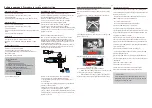
Dismantling of the BD Board
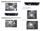
1) Loosen 4 screws “H” on the top of BD Board as shown in fi gure 8.
2) Loosen 1screw “I” at the back panel as shown in fi gure 9.
SERVICE POSITIONS (MAIN UNIT)
Figure 10
Figure 8
Figure 9
Service Position A - MAIN&BD Board
Service Position E - All Boards
Dismantling of the MAIN Board
1) Loosen 6 screws “J” on the top of main board as shown in fi gure 10.
2) Loosen 2 screws “K” at the back panel as shown in fi gure 11
Figure 11
H
I
J
K
Summary of Contents for HTB7250D
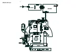
Page 20: ...4 2 4 2 WIRING DIAGRAM V1 V4 V2 V3 V5 SV2 V10 CN901 AC SOCKET SV1 ...
Page 28: ...6 3 6 3 Waveforms for measure point ...
Page 29: ...6 4 6 4 Waveforms for measure point ...
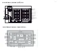
Page 30: ...7 1 7 1 TOUCH BOARD TABLE OF CONTENTS Circuit Diagram 7 2 PCB Layout Top Bottom View 7 3 ...
Page 39: ...10 1 REVISION LIST Version 1 0 Initial release Version 1 1 Add HTB7255D 12 version ...


