


3 - 1
3 - 1
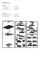
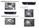
DISASSEMBLY INSTRUCTIONS-MAIN UNIT
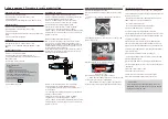
Dismantling of the Top Cover
1) Loosen 1 screw “A” at the back panel to remove the top cover as shown in fi gure 1.
Dismantling of the BT Board
1) Loosen 2 screws “B” on the top of BT board as shown in fi gure 2.
Figure 1
Figure 2
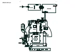
Dismantling of the TOUCH Board
1) Loosen 3 screws “C” at the bracket of Touch Board as shown in fi gure.
Figure 3
Dismantling of the DVD Module
1) Loosen 5 screws “E” at the DVD Module as shown in fi gure 5.
Figure 4
Figure 5
Figure 6
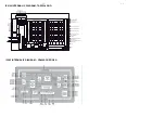
Dismantling of the MP3 &USB &SENSOR Board
1) Loosen 3 screws “F” on the top of MP3&USB Board as shown in fi gure 6
.
2) Loosen 2 screws “G” on the top of SENSOR Board as shown in fi gure 7.
Figure 7
Note:In some service positions the components or copper patterns of one board may risk touching its
neighbouring pc boards or metallic parts. To prevent such short-circuit use a piece of hard paper or
other insulating material between them.
A
B
Dismantling of the VFD Board
1) Loosen 1 screws “D” on the top of VFD Board as shown in fi gure 4.
C
E
F
G
D
Summary of Contents for HTB7250D
Page 20: ...4 2 4 2 WIRING DIAGRAM V1 V4 V2 V3 V5 SV2 V10 CN901 AC SOCKET SV1 ...
Page 28: ...6 3 6 3 Waveforms for measure point ...
Page 29: ...6 4 6 4 Waveforms for measure point ...
Page 30: ...7 1 7 1 TOUCH BOARD TABLE OF CONTENTS Circuit Diagram 7 2 PCB Layout Top Bottom View 7 3 ...
Page 39: ...10 1 REVISION LIST Version 1 0 Initial release Version 1 1 Add HTB7255D 12 version ...


