background image

1

1

2

2

3

3

4

4

5

5

6

6

7

7

8

8

A

A

B

B

C

C

D

D

E

E

F

F

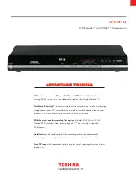
DVDR3375 Front Board Electrical Diagram

To Main Board

To Power Board

TO SWITCH BOARD

C1    B2

C1  B2

C2    B2
C3    B4

C4    B4

C5    B4

C6    B2
C7    B3

C8    C7

C9    C3

C17  D4

C16  C4

C11  C5

C15  C4

C12  C3

C14  C4

C20  D5

C19  D5

C26  E6

C21  D5

C28  E3

C24  D3

C27  E3

C18  D5

C31  C3

C30  B6

C34  B4

C32  D6

C36  E1

C33  B4

C35  B4

C29  B5

D7    D7

D1    B3

D2    B2
D5    C2

D9    E1

D8    C3

D6    D6

FB3  B4

FB11 C4
FB2  B4

FB1  C4

C10  C4

JP3   E5

JP1   B3

J1     E4

JP2   E3

K3    D6

K2    D6

K5    D6

K4    D6

K6    E6

LD1  E4

Q2    B1

Q3    B3

Q4    B2

Q5    B2

Q8    D2

Q7    D2

Q9    E1

R2    B2

R4    B2

R5    B2

R6    B3
R12  B3

R13  B2

R14  B2

R17  E6

R18  C4

R19  D5

R20  D6

R21  D4

R22  D4

R23  D5

R27  D2

R28  E2

R25  D4

R24  D4

R26  D4

R31  E6

R29  E2

R30  E6

R32  E6

R33  E6

R34  E2

R35  D4

R36  E1

R37  E2

R39  C2

R38  E2

R40  C2

R41  C2

R42  E5

R43  C4

R44  C4

R47  E2

R49  E1

R48  E1

S1    E4

U1    B5

U2    C5

U3    C3

U4    D3

Y1    C4

LED1

FAN_CTL

P_CON

IR

OSC_1

CS

D_HOST

RST_MPEG

POW_SW

OSC_1

POW_SW

OSC_2

-24VV

D_FM

RESET

LED1

D_FM

+12V

VCC

RDY_FM

DATA

D_HOST

SCK_MPEG

RDY_FM

POW_SW1

CLK

P_CON

CS

ATN_FM

OSC_2

IR

ATN_FM

SCK_MPEG

DATA

POW_SW

RST_TIME

RST_MPEG

LED2

P_CON

IR

+12V

LED2

FAN_CTL

FAN_CTL

FAN_CTL

P_CON

INT_FP

CLK

IDC_SDA

-24VV

+F2

+F2

+F1

+F1

VCC

-24VV

VCC

VCC

VCC

VCC

VCC

VCC

VCC

Y1

12MHz

U1

VFD Display

35 34

32 31 30 29 28 27 26 25 24 23 22 21 20 19 18 17 16 15 14 13 12 11 10 9 8 7 6 5 4 3 2 1

33

F2 F2

6G 5G 4G 3G 2G 1G NC NC NC NC NC NC NC P1 P2 P3 P4 P5 P6 P7 P8 P9 P10 P11 P12 P13 P14 P15 P16 NP F1 F1

NC

K4

JP1

PITCH=2.0

1

2

3

4

5

6

7

D6

1N4148

R83 1

R28

4K7

K5

C32

NC

S1

R38

10K(OPEN)

R29

1K

R36
NC

+

C4

47uF/16V

D1

1N4148/SM

T

FB2

J1

PICH=2.0

1

2

3

4

5

R40

10K(OPEN)

JP4

PITCH=2.0

1

2

3

4

D8

1N4148/SMT

R14

680

R82 1

FB3

R34

330

JP3

PICH=2.0

1

2

3

4

5

R12

1

C16

0.1u

R27

330

R24

100

C27

NC

+

C7

10UF/50V

R39

10K(OPEN)

C35

100P

R25

100

C28

NC

K2

R26

100

R18

10K

R44

100

C29

0.1u

R41

10K(OPEN)

C17

0.1

D5

5.6V/DIP

C24

0.1u

R42

0(OPEN)

C33

100P

R17

0

U2

PT6312

1 2 3 4 5 6 7 8 9 10 11

12

13

14

15

16

17

18

19

20

21

22

23

24

25

26

27

28

29

30

31

32

33

34

35

36

37

38

39

40

41

42

43

44

SW1 SW2 SW3 SW4 SDout SDin GND SCLK /CS KEY1 KEY2

KEY3

KEY4

VDD

SEG1/K1

SEG2/K2

SEG3/K3

SEG4/K4

SEG5/K5

SEG6/K6

SEG7

SEG8

SEG9

SEG10

SEG11

SEG12

VEE

SEG13

SEG14

SEG15

SEG16

G6

G5

G4

G3

G2

G1

VDD

LED4

LED3

LED2

LED1

GND

OSC

C9

22P

C8

0.1u

R22

10K

D7

1N4148

R35

4K7

+

C5

10uF/50V

R43

1M

R20

0

R19

51K

R4

3.3k

R37

1K

R40

0

R33

10K

+

C3

47uF/16V

R5

3.3k

C30

0.1u

R41

0

+

C25

47uF/16V

R6

680/DIP

R21

10K

C26

100P

R32

10K

C1

104

K6

R31

10K

Q2

2n2222

U3

LH316S

1

2

3

4

5

6

7

8

9

10

11

12

13

14

15

16

17

18

24

23

22

21

20

19

P_CON

DATA

NC

CS

NC

VSS

VSS

CLK

SCL

SDA

DATA_T

RST_TRST_M

IR

D_HOST

D_FM

SCK

VDD

RDY

ATN

OSC2

OSC1

RESET

VDD

R48
33K

K3

C10

22P

C2

104

C11

0.1u

R47

6.8K

C31

100P

C15

0.1u

R49
10K

C19

47P

R16

10K

+

C12

47uF/16V

+

C6

10UF/50V

C20

47P

+

C3

6

47uF/16V

C21

47P

Q3

2n2222/DIP

D9 1N4148

Q8

3906/SMT

R11

1

Q4

2n2222/DIP

FB11

D2

1N4148/SM

T

R23

10K

JP2

PITCH=2.0MM

1

2

3

4

5

6

7

8

C34

100P

Q5

2n2222/DIP

Q9

3904/SMT

R84 1

Q7

3906/SMT

LD1

1

3

2

R30

10K

R2

680/DIP

+

C14

47uF/16V

FB1

C18

NC

U4

REM

1

2

3

IR

GND

VCC

R13

680

6-3

6-3

6-3

6-3

6-3

6-1

6-1

http://www.jdwxzlw.com/?fromuser=华盛维修

家电维修资料网,免费下载各种维修资料

Summary of Contents for DVDR3375

Page 1: ...85 31730 Version 1 0 Service Manual PHILIPS GB Copyright 2006 Philips Consumer Electronics B V Eindhoven The Netherlands All rights reserved No part of this publication may be reproduced stored in aretrieval system or transmitted in any form or by any means electronic mechanical photocopying or otherwise without the prior permission of Philips CLASS 1 LASER PRODUCT Published by TCL KC 0603 Service...

Page 2: ...D MP3 DVD Compression formats Dolby Digital MP3 MPEG2 Multichannel PCM DTS MP3 bit rates 32 256 kbps and VBR Still Picture Playback Disc formats DVD R RW DVD R RW Picture CD Picture Compression formats JPEG Picture enhancement Rotate Zoom and Pan Storage Media Recording speed 2 4x Recording media DVD R RW DVD R RW Front Connections I link DV in IEEE 1394 4pin Video In Audio left right In USB Karao...

Page 3: ...necessary to dismantle Loader or Front Panel It should be remove the front door assembly first Figure 2 If the tray can t open in normal way you can make it through the instruction as figure 3 4 5 Note Make sure to operate gently otherwise it would be damaged Mechanical and Dismantling Instructions 2 1 Figure 1 Figure 2 http www jdwxzlw com fromuser 华盛维修 家电维修资料网 免费下载各种维修资料 ...

Page 4: ...ructions Figure 3 Figure 4 Figure 5 Remove the screws on both side of loader Uplift the bottom of loader The door will fall off automatically Push it gently and the tray will flick out automatically 2 2 http www jdwxzlw com fromuser 华盛维修 家电维修资料网 免费下载各种维修资料 ...

Page 5: ...sconnect the 9 connectors 1 GND cable aiming in the figure then Release the snaps on the both sides of Front Panel and the relative screws on the cabinet finally gently pull the panel out from the set Figure 7 8 2 3 Figure 6 Figure 8 CON3 CON10 CON11 CON6 CON9 CON7 CON4 CON5 GND Cable CON8 CON1 CON2 Mechanical and Dismantling Instructions Figure 7 http www jdwxzlw com fromuser 华盛维修 家电维修资料网 免费下载各种维...

Page 6: ...the relative screws Figure9 Step6 Dismantling Tuner Board first disconnect the 2 connectors then remove the relative screws Figure10 Mechanical and Dismantling Instructions 2 4 Figure 9 CON 13 CON 12 CON 14 CON 15 GND Cable Figure 10 CON 16 CON 17 http www jdwxzlw com fromuser 华盛维修 家电维修资料网 免费下载各种维修资料 ...

Page 7: ...ove the 3 screws on the back of the cabinet then dismantling the IO Board Figure 12 Step9 Dismantling Power Board first disconnect the connector then remove the relative screws Figure 13 Mechanical and Dismantling Instructions 2 5 Figure 11 Figure 13 CON 21 Figure 12 CON 20 CON 18 CON 19 http www jdwxzlw com fromuser 华盛维修 家电维修资料网 免费下载各种维修资料 ...

Page 8: ...s OK button to confirm then screen will display Upgrading software please wait Do not switch off the power 4 The upgraded disc will automatically out when the upgrading complete then take out the disc and power off the set C Read out the software versions to confirm upgrading 1 Power up the set and press system menu button on the remote control 2 Press 0 0 0 9 OK button The software version and ot...

Page 9: ... the U3 s pin 6 8 9 connect condition Correct connection Replace U2 or VFD Yes Yes Yes No Check 24V 12V VCC 5v voltage on the power and front board Check the front board signals on R24 R25 R26 SCK SDA STB 1 Check whether bad solder exists on U2 and pins of VFD 2 Check whether the circuit connected to K2 K3 K4 K5 and K6 is broken Fix the connection JP1 on front board and CN1 on power board http www...

Page 10: ... the P14 of U10 on the AV board is 5v Check the 5v power supply on the AV board Check the P1 of U10 digital audio on the AV board is normal Check P26 of JP2 on Main board signals is normal Fix the connection JP8 on AV board and JP2 on Main board Yes Yes No Go Check the FB8 digital audio on the OP board is normal No digital audio output No 4 2 Yes Yes http www jdwxzlw com fromuser 华盛维修 家电维修资料网 免费下载...

Page 11: ...does not work Yes Replace U2 on the power board Check whether keys on the front board work or not Replace U4 on the power board Replace U1 Yes Check the front board whether P1 of U4 has signal when pressing key on the remote 4 3 http www jdwxzlw com fromuser 华盛维修 家电维修资料网 免费下载各种维修资料 ...

Page 12: ...Board Can t read disc or can t open the disk door Check 40pin cable from main board connection to the loader is normal Check the peripheral components near the J3 on the main board No Go Check whether the DVD loader running is normal Fix the connection the 40pin cable No Yes 4 4 http www jdwxzlw com fromuser 华盛维修 家电维修资料网 免费下载各种维修资料 ...

Page 13: ...isplay Yes Fix the connection power board CN1 front board JP1 Check whether the voltage 12V 5V on the front board is normal Check DC12V to AC 3V switch circuit Replace U2 VFD Yes Check whether the voltage 24V is normal No Check the FB1 on the front board 4 5 http www jdwxzlw com fromuser 华盛维修 家电维修资料网 免费下载各种维修资料 ...

Page 14: ...Check the cable connection fan to Power board CN3 Go No No Fan don t work Yes Check R9 on Power board Check on Power board whether P1 of CN3 is 12v Replace the cable Replace Fan Yes 4 6 http www jdwxzlw com fromuser 华盛维修 家电维修资料网 免费下载各种维修资料 ...

Page 15: ...Board Can t read disc or can t open the disk door Check 40pin cable from main board connection to the loader is normal Check the peripheral components near the J3 on the main board No Go Check whether the DVD loader running is normal Fix the connection the 40pin cable No Yes 4 7 http www jdwxzlw com fromuser 华盛维修 家电维修资料网 免费下载各种维修资料 ...

Page 16: ...FORNT PANEL KEY IR VFD AUDIO IN 2 C WM8776 POWER Pr Pb BUFFER AUDIO IN 1 Y AUDIO RCH Pb WM8776 AUDIO ADC 1394 PHY TUNER EEROM Pr AUDIO LCH DMN8602 TUNER SDRAM Y 1EEE1394 S PDIF BUFFER CVBS Y AUDIO DAC Y DVDR3375 Block Diagram 5 1 5 1 http www jdwxzlw com fromuser 华盛维修 家电维修资料网 免费下载各种维修资料 ...

Page 17: ... 2MM 1 2 3 4 5 6 7 8 9 CN6 CON9 2MM 1 2 3 4 5 6 7 8 9 J10 CON 05 2 0mm 1 2 3 4 5 J5 HEADER 20X2 1 2 3 4 5 6 7 8 9 10 11 12 13 14 15 16 17 18 19 20 21 22 23 24 25 26 27 28 29 30 31 32 33 34 35 36 37 38 39 40 JP2 FMN32 1 0mm 1 2 3 4 5 6 7 8 9 10 11 12 13 14 15 16 17 18 19 20 21 22 23 24 25 26 27 28 29 30 31 32 XP5 PICH 2 0 1 2 3 4 5 CN4 CON9 2MM 1 2 3 4 5 6 7 8 9 JP1 PH7 2MM 1 2 3 4 5 6 7 CN1 PH7 2M...

Page 18: ... 3 4 5 6 7 D6 1N4148 R83 1 R28 4K7 K5 C32 NC S1 R38 10K OPEN R29 1K R36 NC C4 47uF 16V D1 1N4148 SMT FB2 J1 PICH 2 0 1 2 3 4 5 R40 10K OPEN JP4 PITCH 2 0 1 2 3 4 D8 1N4148 SMT R14 680 R82 1 FB3 R34 330 JP3 PICH 2 0 1 2 3 4 5 R12 1 C16 0 1u R27 330 R24 100 C27 NC C7 10UF 50V R39 10K OPEN C35 100P R25 100 C28 NC K2 R26 100 R18 10K R44 100 C29 0 1u R41 10K OPEN C17 0 1 D5 5 6V DIP C24 0 1u R42 0 OPEN...

Page 19: ...DVDR3375 Front Board Print layout Bottom Side DVDR3375 Front Board Print layout Top Side DVDR3375 Switch Board Print layout 6 2 6 2 http www jdwxzlw com fromuser 华盛维修 家电维修资料网 免费下载各种维修资料 ...

Page 20: ...GND USB_GND GND_AIN VCC VCC GND_AIN V33 GND_PHY_A V33 CHASSIS_GND USB_GND XS1 PH7 2MM 1 2 3 4 5 6 7 R13 10K U3 CM1213 1 CH1 2 VN 3 CH2 CH3 4 VP 5 CH4 6 D4 BAT54S 1 3 2 D6 1N4148 1 2 D2 BAT54S 1 3 2 R9 1K D5 1N4148 1 2 CON4 MIC 1 2 3 4 5 6 U2BB NJM4580E 5 6 7 8 4 R11 47K C9 0 1UF D7 LVS C10 0 1UF R18 22K C4 100P FB1 BK1608HM601 T R19 10K R14 1 5K D8 LVS XS5 PH7 2MM 1 2 3 4 5 6 7 C15 100U D9 LVS R4 ...

Page 21: ...6 4 DVDR3375 Input Board Print layout 6 4 http www jdwxzlw com fromuser 华盛维修 家电维修资料网 免费下载各种维修资料 ...

Page 22: ...AV GND_AV VCC GND_AV VCC VCC GND_AV GND_AV D7 1N4148 1 2 C18 33PF 0PEN FB2 BK1608HM121 T JP2 FMN6 2 0mm 1 2 3 4 5 6 C9 33PF C15 33PF OPEN FB13 BK1608HM121 T FB3 BK1608HM121 T FB6 BK1608HM121 T C17 220UF 16V J3 FMN6 2 0mm 1 2 3 4 5 C10 0 1UF FB12 BK1608HM121 T D11 1N4148 1 2 D9 1N4148 1 2 C1 220UF 16V D4 1N4148 1 2 J1 FMN6 2 0mm 1 2 3 4 5 6 7 8 9 C12 10PF C11 100UF 16V D10 1N4148 1 2 FB11 BK1608HM6...

Page 23: ...6 6 DVDR3375 IO Board Print layout 6 6 http www jdwxzlw com fromuser 华盛维修 家电维修资料网 免费下载各种维修资料 ...

Page 24: ... 9015 Q5 9014 PAS PAS C25 10nF R22 22k ZD4 15V 1 2W C23 0 1uF PAS Q2 9014 D7 1H8 U3 PC123X 1 2 4 3 C19 0 1uF PAS C9 473 400v ZD6 18V 1 2W R5 2 2k PAS T1 EC28 15 10 1 13 4 2 14 7 6 5 11 8 9 12 R19 470 U5 TL431 2 1 3 R6 22k D1 1N4007 PAS U2 FSDM0565RN 2 1 4 5 6 3 SOURCE DRAIN VFB N C Vatr VCC R15 4 7k Q6 9015 C26 1000uF 16V PAS D3 1N4007 C11 47uF 25V R32 4 7k 1 D8 FR102 PAS D5 FR104 R17 10k C1 333 4...

Page 25: ...6 8 DVDR3375 Power Board Print layout 6 8 http www jdwxzlw com fromuser 华盛维修 家电维修资料网 免费下载各种维修资料 ...

Page 26: ... F VDENC 0 1 2 CPST Y C CPST G Y Y B Pb C CPST R Pr C CPST SEL PEC GPIOx 45 GPIOx 29 2nd 24 bit VI_D0 VI_D1 VI_D2 VI_D3 VI_D4 VI_D5 VI_D6 VI_D7 VI_D8 VI_D9 VO_D16 VO_D17 VO_D18 VO_D19 VO_D20 VO_D21 VO_D22 VO_D23 VIO GPIOx 30 GPIOx 0 GPIOx 1 GPIOx 2 GPIOx 3 GPIOx 4 GPIOx 5 GPIOx 6 GPIOx 7 GPIOx 8 GPIOx 9 GPIOx 10 GPIOx 11 GPIOx 12 GPIOx 13 GPIOx 14 GPIOx 15 VOUT VIN JTAG SYSTEM GPIOx 31 GPIOx 34 GP...

Page 27: ...RAM_DQ29 E5_SDRAM_DQ22 SDRAM_DQM3 SDRAM_DQ9 SDRAM_CLKE SDRAM_DQ28 SDRAM_DQ7 SDRAM_A1 SDRAM_A10 SDRAM_DQ8 SDRAM_DQ12 SDRAM_A14 E5_SDRAM_DQ20 E5_SDRAM_DQ3 SDRAM_DQ30 SDRAM_DQ27 SDRAM_DQ20 E5_SDRAM_DQ23 SDRAM_DQ0 SDRAM_DQ24 SDRAM_DQM2 SDRAM_DQ17 SDRAM_A5 E5_SDRAM_DQ6 SDRAM_DQ24 E5_SDRAM_DQ2 SDRAM_DQ7 SDRAM_DQ10 SDRAM_DQ15 SDRAM_DQS0 E5_SDRAM_DQM2 E5_SDRAM_A3 SDRAM_CLK 1 VREF E5_SDRAM_A14 SDRAM_A8 E5_...

Page 28: ...RAM_A14 SDRAM_DQS1 SDRAM_DQS2 SDRAM_CLK1 SDRAM_A4 SDRAM_CLK0 SDRAM_DQM3 SDRAM_A9 SDRAM_A3 SDRAM_A1 SDRAM_A9 SDRAM_A12 SDRAM_A4 SDRAM_CLKE SDRAM_A1 SDRAM_DQ 31 0 SSTL2_VDD SSTL2_VDD GND SSTL2_VDD SSTL2_VDD GND GND GND GND GND SSTL2_VDD GND C96 0 1UF C95 0 1UF U25 16MX16 DDR 29 30 31 32 35 36 37 38 39 40 28 41 26 27 24 44 23 22 21 20 47 65 63 62 60 59 57 56 13 11 54 10 8 7 5 4 2 16 51 45 46 1 18 33 ...

Page 29: ...E5_OE HD0 HD6 E5_MA5 AI_MCLKO E5_GPIOx5 E5_GPIOx2 Y_Out Pr R_Out HD11 SYS_RST AO_MCLKO HD3 E5_UART2_RX CVBS_IN AO_FSYNC E5_GPIOx42 E5_SPI_MISO HD2 SDA VI_GPIO_C1 E5_ALE R_Y_IN AO_IEC958 HD13 SCL AO_D3 AO_D2 AO_D1 VI_GPIO_C2 VI_GPIO_C3 GND V33 V33 V33 GND_VIN GND GND VCC GND_VIN GND GND GND GND V33 GND GND VO_GND GND_VIN VCC V33 GND FB18 BK1608HM121 T R532 0 FB30 BK1608HM121 T FB129 BK1608HM601 T F...

Page 30: ...iAddr4 ATAPI_DATA3 SCL HD 15 0 ATAPI_DATA9 E5_WEL ATAPI_INTRQ ATAPI_DMARQ ATAPI_DATA12 ATAPI_DIOW_L ATAPI_DATA6 AtapiAddr3 AtapiAddr0 ATAPI_DATA11 HD 15 0 AtapiAddr1 E5_MA22 E5_MA1 V33 V33 GND V33 VCC V33 V33 V33 V33 VCC V33 FB68 BK1608HM121 T R111 82 FB82 BK1608HM121 T FB70 BK1608HM121 T R124 10K SKT U1 SKT TSOP48 C251 0 1UF FB72 BK1608HM121 T R113 82 JP1 DNS HEADER 3X1 1 2 3 FB74 BK1608HM121 T R...

Page 31: ...D_PHY_D CHASSIS_GND V33_PHY_D V33_PHY_D GND_PHY_A GND_PHY_D GND_PHY_D GND_PHY_D GND_PHY_A VCC GND_PHY_D GND_PHY_D GND_PHY_D V33_PHY_A GND_PHY_A V33 V33_PHY_D GND_PHY_A GND_PHY_A TPB PHY_PC1 TPA PHY_PC0 PHY_PC2 PHY_R1 TPA PHY_R0 PHY_ISO TPB R81 10K Y2 24 576MHz C52 12PF C353 1000PF C51 12PF R84 10K R74 DNS 10K C53 0 1UF T1 YB019T 221 1 4 2 3 5 6 7 8 C65 0 1UF R76 10K C358 0 1UF C67 0 1UF C66 0 1UF ...

Page 32: ...5 220UF 10V J1 PH10 2MM 2MM PH10 TH 1 2 3 4 5 6 7 8 9 10 L7 FBMJ2125HS420 T CA15 220UF 10V FB4 FBMJ3216HS800 T MT1 MountHole 1 2 3 4 5 6 7 8 9 H 2 34 5 6 7 8 9 FB100 FBMJ2125HS420 T MT2 MountHole 1 2 3 4 5 6 7 8 9 H 2 34 5 6 7 8 9 CA12 220UF 10V CA8 220UF 10V CA22 47UF 10V R362 DNS_1K C403 0 1UF C39 0 1UF C37 0 1UF FB93 FBMJ2125HS420 T CA7 220UF 10V FB94 FBMJ2125HS420 T C131 0 1UF FB1 FBMJ3216HS80...

Page 33: ... R400 75 0805 C399 0 1UF C370 0 1UF R401 75 0805 CA38 100UF 10V C371 0 1UF C122 0 1UF R402 10K 0805 C372 0 1UF R396 75 0805 L8 2 7UH 0805 R403 75 0805 C369 0 1UF C373 0 1UF U38 TVP5146 TQFP 80 1 2 3 4 5 6 7 8 9 10 11 12 13 14 15 16 17 18 19 20 21 22 23 24 25 26 27 28 29 30 31 32 33 34 35 36 37 38 39 40 41 42 43 44 45 46 47 48 49 50 51 52 53 54 55 56 57 58 59 60 61 62 63 64 65 66 67 68 69 70 71 72 ...

Page 34: ...DVDR3375 Main Board Print layout Top Side 6 17 6 17 http www jdwxzlw com fromuser 华盛维修 家电维修资料网 免费下载各种维修资料 ...

Page 35: ...6 18 6 18 DVDR3375 Main Board Print layout Bottom Side http www jdwxzlw com fromuser 华盛维修 家电维修资料网 免费下载各种维修资料 ...

Page 36: ...34 56PF R41 10K OPEN C13 0 1UF C32 1500PF R263 10 R38 10k C76 47UF 16V 1 2 C439 100U C73 0 1UF C200 10U R240 10K C31 100UF 16V 1 2 Y2 32 768K R261 10K C33 0 01UF U3 MSP3455G PMQFP44 7 8 9 10 11 12 13 14 15 16 17 18 19 20 21 22 25 26 27 23 24 28 29 30 31 32 33 34 35 36 37 38 40 41 42 43 44 1 2 3 39 4 5 6 TP D_CTR_I O_1 D_CTR_I O_0 ADR_SEL STANDBYQ I2C_SCL I2C_SDA I2S_CL I2S_WS I2S_DA_OUT I2S_DA_IN1...

Page 37: ...Vin GND_Vin GND_AV VCC GND_Vin GND_AV V12 GND_Vin V33 GND_Vin VCC_VOUT VCC GND_Vout GND_Vout VCC_VOUT VCC_TUNER GND_Vout GND_Vin GND_AV GND_Vout V12 VCC_VOUT GND_Vin C249 10UF 16V 1 2 D35 1N4148 1 2 FB46 BK1608HM121 T R159 75 FB55 BK1608HM121 T FB34 L12 0 47UH C158 1000PF FB40 BK1608HM121 T C152 220PF R56 NC FB62 D24 1N4148 1 2 FB24 FBA04HA450BA Q27 2N3906 C134 0 1uF R64 100k L11 0 47UH FB39 BK160...

Page 38: ...DVDR3375 AV Board Print layout Top Side 6 21 6 21 http www jdwxzlw com fromuser 华盛维修 家电维修资料网 免费下载各种维修资料 ...

Page 39: ...6 22 6 22 DVDR3375 AV Board Print layout Bottom Side http www jdwxzlw com fromuser 华盛维修 家电维修资料网 免费下载各种维修资料 ...

Page 40: ...7 1 MECHANICAL EXPLODED VIEW ASSY_1 ASSY_1 http www jdwxzlw com fromuser 华盛维修 家电维修资料网 免费下载各种维修资料 ...

Page 41: ...965 000 32463 DC BRUSHLESS FAN 4010L12F 39 9965 000 33784 SCART EARTH PATCH 40 9965 000 32464 BACK CABINET PLATE 42 9965 000 32465 POWER CORD 1 8M ASSY_1 9965 000 33780 ASS Y FRONT DOOR ASSY_2 9965 000 33781 ASS Y FRONT CABINET AV_CBL 9965 000 20384 AUDIO VIDEO CABLE 1 5M BE_AT_CBL 9965 000 26567 ATAPI CABLE 40P 27CM BE_PS_CBL 9965 000 26569 SUPPLY WIRE 4P 38CM DRIVE DV_IN_CBL 9965 000 33774 DV IN...

Page 42: ...8 1 REVISION LIST Version 1 0 Initial release http www jdwxzlw com fromuser 华盛维修 家电维修资料网 免费下载各种维修资料 ...

Reviews: