made in small steps. Do not adjust any one point more than 1/4 the distance of one grid in each pass.
After the left most line is adjusted, start at the center left of the screen and work to the right, aligning the
Horizontal lines. When adjusting the Horizontal lines, best results are obtained when working from left to
right. After the Center line is adjusted, go to the next line down until all of the lines have been adjusted,
then work from the center up to adjust the Horizontal lines. Using the same method, work from center
out to adjust the Vertical lines. At least three passes will be necessary to complete the alignment. Press
the Index button to return to the selection menu.
When the Green geometry is complete, Store the data. Remove the Template from the screen.
Select Red to Green in the selection menu. Using the same method that was used to adjust the
Green Grid to the Template, adjust the Red Grid onto the Green Grid. If the set is a later produc-
tion, select SP RED to center the Red grid onto the Green grid. Exit this mode by pressing the
Menu button. Then select the MP RED to adjust the Red onto the Green using the 35-point adjust-
ment. When this is complete, select the RED TO GREEN to perform the 208-point adjustment.
When the RED TO GREEN is complete, select the BLUE TO GREEN using the same alignment
method as the RED TO GREEN.
Select STORE to save your the alignments after adjusting each color. Each time data is stored; the
Intellisense circuit will recalculate the position of the four sensors in the set. The Epic plus version only
has the Intellisense. Exiting the Convergence Mode without saving will cause the alignments to be lost.
Repeat the adjustment for each of the remaining modes.
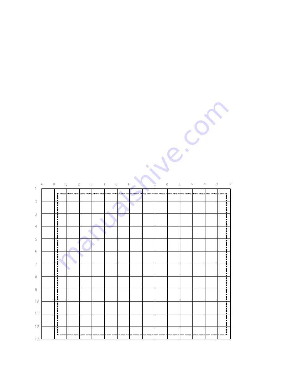
FIGURE 46 - INTERNALLY GENERATED CONVERGENCE PATTERN
Page 71
Summary of Contents for DPTV400 Series
Page 9: ...7 FIGURE 3 EPIC REAR JACK PANEL Page 6 ...
Page 14: ...FIGURE 6 STANDBY POWER SUPPLY Page 11 ...
Page 15: ...FIGURE 7 MAIN POWER SUPPLY Page 12 ...
Page 20: ...FIGURE 11 HORIZONTAL OUTPUT Page 17 ...
Page 21: ...FIGURE 12 HIGH VOLTAGE Page 18 ...
Page 22: ...FIGURE 13 VERTICAL AMPLIFIER Page 19 ...
Page 25: ...FIGURE 15 VIDEO SIGNAL FLOW BLOCK Page 22 ...
Page 26: ...FIGURE 16 SIDE JACK PANEL Page 23 ...
Page 27: ...FIGURE 17 SSM NTSC AV INPUTS AND SWITCHING Page 24 ...
Page 29: ...FIGURE 18 NTSC SSB SIGNAL PROCESSING Page 26 ...
Page 30: ...FIGURE 19 HD ATSC BLOCK Page 27 ...
Page 31: ...FIGURE 20 EPIC ATSC BLOCK Page 28 ...
Page 32: ...FIGURE 21 HD DW MODULE Page 29 ...
Page 35: ...FIGURE 23 AV3 AND AV4 INPUTS AND SWITCHING Page 32 ...
Page 38: ...FIGURE 25 SSM VIDEO DRIVE Page 35 ...
Page 41: ...FIGURE 26 SHARPNESS CONTROL Page 38 ...
Page 42: ...FIGURE 27 TINT CONTROL Page 39 ...
Page 43: ...FIGURE 28 CRT DRIVE Page 40 ...
Page 45: ...FIGURE 30 CRT PANEL Page 42 ...
Page 47: ...FIGURE 31 AUDIO SIGNAL FLOW BLOCK Page 44 ...
Page 48: ...FIGURE 32 SSB AUDIO PROCESSING Page 45 ...
Page 49: ...FIGURE 33 AUDIO AMPLIFIER Page 46 ...
Page 52: ...FIGURE 35 CONVERGENCE PROCESSOR Page 49 ...
Page 53: ...FIGURE 37 INTELLISENSE SENSING CIRCUIT Page 50 ...
Page 55: ...FIGURE 38 CONVERGENCE HORIZONTAL DRIVE Page 52 ...
Page 56: ...FIGURE 39 VERTICAL CONVERGENCE DRIVE Page 53 ...
Page 58: ...FIGURE 40 SET CONTROL AND I2C BUSSES Page 55 ...
Page 59: ...FIGURE 41 OSD SIGNAL PATH Page 56 ...
Page 62: ...Figure 59 FIGURE 42 WIRING INTERCONNECT ...
Page 71: ...FIGURE 44 SAM MENUS Page 68 ...
Page 77: ......
Page 78: ...MMARTIN 04 13 04 ...


