background image

6

7

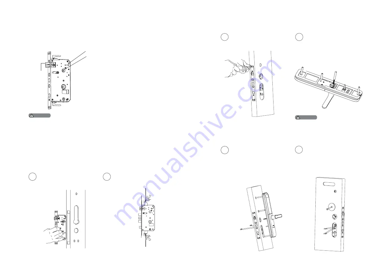
1. Choose a proper installation kit based on the door thickness;

2. The default tool kit is applicable to doors of 38-60mm thick. If your door thickness is out of this 
range, please contact us.

Step 3 | Change the latch bolt direction

You can change the direction of the latch bolt to adapt to doors of different 
opening directions.

Latch bolt

Directional screw

Inverting tailpiece

1. Push the inverting tailpiece to the top.

2. Press into the latch bolt and turn it 180 

degrees, then pull out the latch bolt.

3. Push the tailpiece to the bottom.


4. Change the direction of the directional 

screw according to the internal and external 

door opening requirements.

(Directional screws must be installed on the 

inside of the door, that is, which side is the 

directional screw and which side must be the 

inner escutcheon)

1

Use the drilling template to drill 

the needed holes on the door and 

mount the mortise into the door.

Hook up the multi-lock latch bolt 

when the mortise is inserted. 

(This step is unneeded when 

installing wooden doors.)

2

Installation steps

Pass the cable through the hole 

on the door. The mechanical key 

tailpiece needs to be inserted 

into the two rotary holes on 

the mortise, so that the outer 

escutcheon stays close to the 

outside door.

Tighten the 4 anchor screws on 
the mortise. 

The mechanical key tailpiece shall be 
appropriately cut as per the thickness of 
the door, and the square shaft, connecting 
screw tube and anchor screw tube with the 
appropriate length shall also be used.

Install the connecting screw tubes 

and mechanical key tailpiece on the 

outer escutcheon, and insert the 

compressed spring and square shaft 

into the handle hole (the compressed 

spring faces the handle side).

3

4

Tighten the mounting plate with an 

anchor screw against the inside of 

the door. 

5

6

The following installation steps apply to right-open doors. For left-open doors, 

please read the chapter [Pre-installation instructions] carefully and make 

needed adjustments.

Attention

Attention

Summary of Contents for DDL172LKCC0/97

Page 1: ......

Page 2: ...tory settings One button mute function Door lock status indicator Low battery indicator Mute mode indicator System lock indicator Alarm types and alarm modes How to apply an emergency power How to replace batteries Modify Master PIN code User settings Delete a user System settings Extended functions System query Local Query Unlock Unlock from outside With PIN code With fingerprint With card Unlock...

Page 3: ...e lock by yourself Keep the relevant sealed stickers properly Do not easily disclose the password information Please modify the default master PIN code immediately after finishing installing and debugging and keep the mechanical key properly Please replace all the batteries immediately if there is a low battery alarm Please make sure to correctly match the poles when installing the batteries Cauti...

Page 4: ... cover x1 16 Inside escutcheon lower cover x1 17 Rotary knob tailpiece x1 Pre installation instructions Step 1 Check the door opening direction This product can be installed on doors of 4 types of opening directions left out pull right in push right out pull and left in push Step 2 Change the handle direction Remove the 2 cross recessed countersunk head screws in the escutcheon 1 Rotate the handle...

Page 5: ...e mortise into the door Hook up the multi lock latch bolt when the mortise is inserted This step is unneeded when installing wooden doors 2 Installation steps Pass the cable through the hole on the door The mechanical key tailpiece needs to be inserted into the two rotary holes on the mortise so that the outer escutcheon stays close to the outside door Tighten the 4 anchor screws on the mortise Th...

Page 6: ... 2 anchor screws Install the batteries then the battery cover and the inside lower cover Try the inside and outside handles the rotary knob the mechanical key and check if all components are well connected 7 8 9 10 Keypad Card reader Mute button Low battery indicator Fingerprint sensor Lever Door status indicator Reset button Emergency power interface Mechanical key hole Battery cabinet Lever Safe...

Page 7: ...ystem 1 2 Register a user PIN code Enter a one time user PIN code of 6 to 12 digits and press to confirm Re enter and press to confirm After hearing a voice prompt of Succeeded press several times until you exit master mode Press 2 to enter user settings then press 2 againtoenterone timePINcoderegistration 2 2 Unlock with any registered identity information Unlock with any two of PIN code card and...

Page 8: ...aring a voice prompt of Succeeded press several times until you exitmastermode Delete a one time user PIN code Press enter master PIN code and press to confirm Press 3 to enter user deletion then press 2 to enter one time user PIN code deletion After hearing a voice prompt of Succeeded press several times until you exit master mode Delete a fingerprint Press enter master PIN code and press to conf...

Page 9: ...en 5 to enter time settings Enter the time and confirm with 4 4 4 4 System settings Switch to dual verification mode Date settings Time settings Security Code query 3 2 4 3 or or 2 1 Volume settings Press enter master PIN code and press to confirm Press 4 to enter system settings then press 2 to enter volume settings Adjust the volume as needed For higher volume press 1 for lower volume press 2 fo...

Page 10: ...a voice prompt of Door opened press the handle to open the door 1 Place your registered card on the card reader 2 After hearing a voice prompt of Door opened press the handle to open the door With handle 2 1 2 2 3 1 1 Lock Lock from outside inside Lift the handle after closing the door Then the bolt will pop up and door will be locked Lift the handle after closing the door Then the bolt will pop u...

Page 11: ... inside and prevent unlocking from inside How to use 1 Enable safe handle function Toggle the switch to red scale 2 Disable safe handle function Toggle the switch to green scale 6 Other functions Push Restorefactorysettings onebuttontorestore to factory settings Function Empty all user information and return to factory settings How to use Long press the RES button for 5 seconds and all the user in...

Page 12: ...ll be a voice prompt of Low battery Please replace all batteries Lock status indicator Low battery indicator 7 Meanings Use of the indicators Colorsofthelightandthecorresponding meanings 1 White Indicates the mute mode is off 2 Green Indicates the mute mode is on Mute mode indicator System lock indicator 3 flashes 2 flashes 1 flash If there are 10 consecutive and incorrect inputs of any ofthe3type...

Page 13: ...ms Turning off Auto close or close after a successful key verification or close after the normal indoor unlock How to use an emergency power How to replace batteries When the battery voltage is insufficient and the door cannot be power up from the outside you can power the lock through the Micro USB interface by using a 5V power bank as an emergency power supply After opening the door lock please ...

Page 14: ...klijke Philips N V and are used under license This product has been manufactured by and is sold under the responsibility of Shenzhen Conex Intelligent Technology Co Ltd and Shenzhen Conex Intelligent Technology Co Ltd is the warrantor in relation to this product Version 2 0 ...

Reviews: