background image

User Manual BDS4222B/V/R

12

4.2

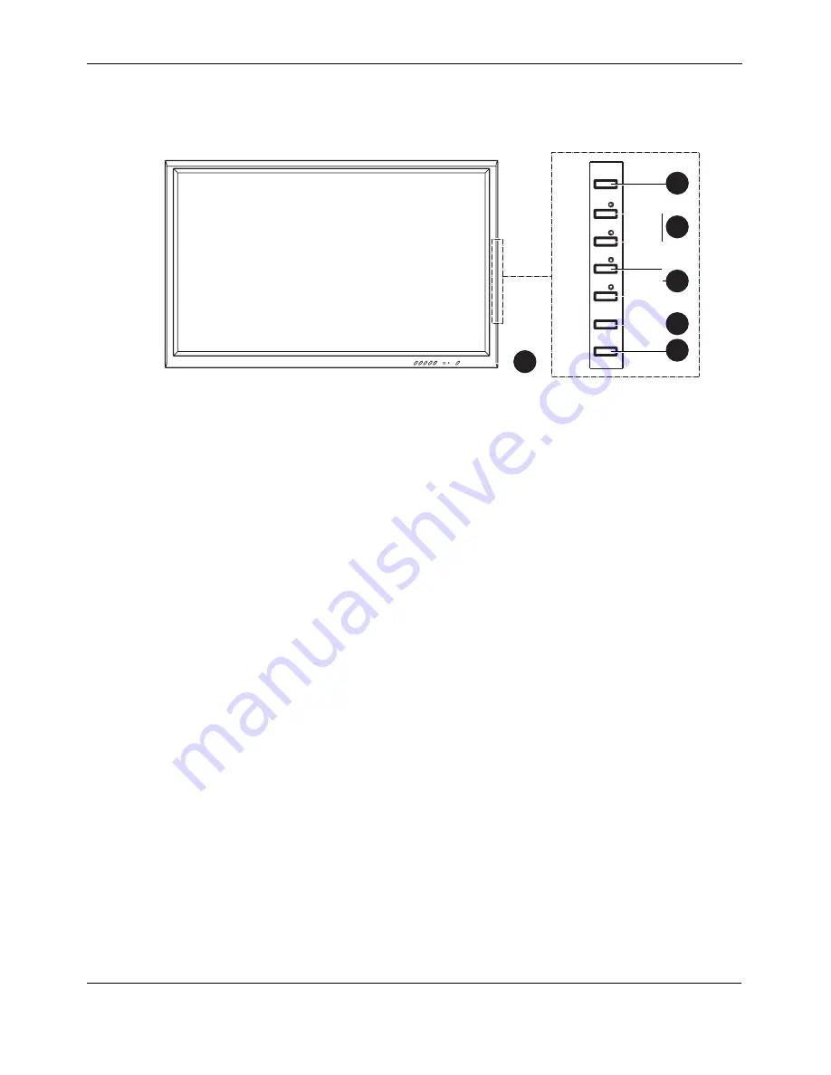
FRONT  VIEW

1. Status LED

Not Illumated = No  AC Power  detected

If the main power switch (rear of panel) is turned off,  this  LED 
will not illuminate.

Orange = Standby (Power OFF) with AC power  
detected

The LED  will illuminate in orange  color if the monitor is shut off 
but the main power cord is plugged into the back of the  unit.

Solid Green = Power ON

2. Power (Standby) Button

Turns power on/off from standby mode.  There is a wait period 
between on/off cycles.

3. Volume Adjustment Buttons

Use these buttons to adjust volume up and down. These keys also 
serve as navigation and adjustment keys when On Screen Display 
menu is engaged.

4. Select Buttons

Use these buttons to navigate through the the On Screen Display 
menu. If an optional TV tuner is installed, these buttons also function 
as Channel Up/Down.

5. Menu Button

Use this button to engage the On Screen Display menu.

6. Input Button

Use this button to switch between available inputs.

POWER

VOL.

VOL.

SEL.

SEL.

MENU

INPUT

2

1

5

6

3

4

Summary of Contents for BDS4222B

Page 1: ...Philips Business Solutions User Manual EN TYPE Nr BDS4222B BDS4222V BDS4222R ...

Page 2: ......

Page 3: ...ection 18 5 5 Connecting a PC 19 6 BASIC FUNCTIONS 21 6 1 Powering ON OFF 21 6 2 Selecting Signal Source 21 6 3 Volume Adjustment 22 6 4 On screen Display menu 23 6 5 On Screen Display Status 23 6 6 Understanding Widescreen Modes 24 6 6 1 4 3 Square Content 24 6 6 2 Widescreen Content 24 6 7 Changing Aspect Ratios 25 7 ADVANCED FUNCTIONS 27 7 1 Picture Controls 27 7 1 1 Adjusting Picture Settings ...

Page 4: ...nnel Search 42 7 9 3 Channel Edit 43 7 10 On Screen Status Display TV Mode BDS4222R only 43 7 10 1 Changing Channels 43 7 10 2 Sound Type 44 8 TECHNICAL SPECIFICATIONS 45 8 1 Specifications 45 9 CLEANING AND TROUBLESHOOTING 49 9 1 Cleaning 49 9 2 Troubleshooting 50 10 LIMITED WARRANTY EUR 51 11 LIMITED WARRANTY USA 55 ...

Page 5: ...equipment or usage of an unshielded connecting cable may cause excessive interference Adjust only those controls that are covered by the operating instructions Improper adjustment of other controls can result in damage which often requires extensive work by a qualified technician to restore the unit to normal operation Use in well ventilated area and do not block any of the ventilation openings In...

Page 6: ...The power supply cord or the plug has been damaged or frayed Objects have fallen or liquid has been spilled into the appliance The appliance has been exposed to rain The appliance does not appear to operate normally or exhibits a marked change in perfomance The appliance has been dropped or the enclosure damaged Unit does not operate normally when the operating instructions are followed Tilt Stabi...

Page 7: ... or carbon and alkaline etc Remove batteries when the unit is not used for a long time 1 2 WARNINGS AND PRECAUTIONS 1 2 1 NOTE TO THE CATV SYSTEM INSTALLER This reminder is provided to call the CATV system installer s attention to Article 820 40 of the NEC that provides guidelines for proper grounding and in particular specifies that the cable ground must be connected to the grounding system of th...

Page 8: ...y wipe the cabinet surfaces with a clean cloth or sponge dampened in a solution of cool clear water Use a clean dry cloth to dry the wiped surfaces Occasionally vacuum the ventilation holes or slots in the cabinet back Never use thinners insecticide sprays or other chemicals on or near the cabinet as they might cause permanent marring of the cabinet finish Do not allow a still image to be displaye...

Page 9: ...lowing measures Reorient or relocate the receiving antenna Increase the separation between the equipment and the receiver Connect the equipment into an outlet on a circuit different from that to which the receiver is connected Consult the dealer or an experienced radio TV technician for help Operation of this equipment in a residential area is likely to cause harmful interference in which case the...

Page 10: ...User Manual BDS4222B V R 8 ...

Page 11: ...rate are installed on the front of the product Since both glass can be broken and scraped easily the product has to be handled with care Never place the monitor with the glass faced down unless it is protected with pads After opening the carton ensure that the content is in good condition and complete When possible use the handles on the back of the monitor for transport 3 2 PACKAGE CONTENTS Pleas...

Page 12: ...e back of the product and the wall should be maintained for proper ventilation Avoid installing the product in the kitchen bathroom or any other places with high humidity so as not to shorten the service life of the electronic components Please ensure the product is installed horizontally Any 90 degrees clockwise or counter clockwise installation may induce poor ventilation and subsequent componen...

Page 13: ...tions vary according to monitor type The functionality of each monitor type is shown in the table below BASIC FUNCTIONALITY VIDEO FUNCTIONALITY TV MONITOR TYPE Nr VGA DVI VGA DVI Audio In SCART AV Component Video Audio In S Video AntennaJack TV Tuner BDS4222B 3 3 3 BDS4222V 3 3 3 3 3 3 BDS4222R 3 3 3 3 3 3 3 ...

Page 14: ...rns power on off from standby mode There is a wait period between on off cycles 3 Volume Adjustment Buttons Use these buttons to adjust volume up and down These keys also serve as navigation and adjustment keys when On Screen Display menu is engaged 4 Select Buttons Use these buttons to navigate through the the On Screen Display menu If an optional TV tuner is installed these buttons also function...

Page 15: ...4222R only Connect to TV or CATV antenna 5 Digital DVI Input Connect to digital video signals from a Set Top box or Computer 6 RGB VGA Input Connect to RGB VGA output of Computer or Set Top box 7 RGB VGA Output Connect to another computer monitor for daisy chaining applications 8 RS 232 Connector For factory use only 9 SCART AV Connector BDS4222V BDS4222R only Connect to external sources such as V...

Page 16: ...main and sub picture windows under PIP or POP modes See page 30 8 Standby Power On Off Push this button to switch on the monitor from Standby mode Push it again to turn it off to Standby mode 9 Input Select Selects the input signal modes sequentially See page 21 10 Channel Up Down Changes the TV channels sequentially BDS4222R only 11 PIP Picture in Picture Button Activates the PIP Picture in Pictu...

Page 17: ...ING TV OR CATV Using ANT input BDS4222R only 1 Connect the RF cable from the antenna or cable socket to the antenna input ANT of the monitor COMPONENT VI DEO AUDIO I N AUDIO O UT AUDIO I N VIDEO I N R Y L L R R DVI RGB S VIDEO L L R PB CB PR CR SCART INPUT 2x ANT AIR or CABLE ...

Page 18: ...e S VIDEO connector Using TV Input BDS4222R only 1 Connect the antenna out socket of the videorecorder to the antenna input ANT of the monitor 2 Connect the videorecorder to the antenna wall socket or cable box COMPONENT VI DEO AUDIO I N AUDIO O UT AUDIO I N VIDEO I N R Y L L R R DVI RGB S VIDEO L L R PB CB PR CR RF A ntenna C able VCR ANT SCART INPUT 2x COMPONENT VI DEO AUDIO I N AUDIO O UT AUDIO...

Page 19: ... to the R and L audio in jacks of the monitor Using S Video Input BDS4222V BDS4222R only 1 Connect the S Video 4 pin DIN connector of the DVD to the S VIDEO input of the monitor 2 Connect the red R and white L audio jacks of the DVD to the R and L audio in jacks located next to the S VIDEO connector COMPONENT VI DEO AUDIO I N AUDIO O UT AUDIO I N VIDEO I N R Y L L R R DVI RGB S VIDEO L L R PB CB P...

Page 20: ...See page 35 for more information Connecting External Amplified Speakers This monitor can be connected to an external set of amplified speakers using the AUDIO OUT jacks located on the back of the monitor 1 Connect the red R and white L AUDIO OUT jacks to the external amplified speakers COMPONENT VI DEO AUDIO I N AUDIO O UT AUDIO I N VIDEO I N R Y L L R R DVI RGB S VIDEO L L R PB CB PR CR SCART INP...

Page 21: ...r Windows The display settings for a typical Windows based computer are shown below However the actual screens on your computer will differ depending on the version of Windows and video card equipped with the computer Even though the actual screen may look different from example displayed below basic set up routine will apply in most cases 1 Go to the Window s CONTROL PANEL by clicking START SETTI...

Page 22: ...User Manual BDS4222B V R 20 ...

Page 23: ... key on the monitor panel or the remote control The monitor will now turn on after a brief pause The STATUS LED will now turn green to indicate power on status 2 Turn off the power by pressing the POWER key on the front panel or the remote control again 6 2 SELECTING SIGNAL SOURCE Using Front Panel or Remote Control 1 Press the INPUT key on the monitor panel or the AV key on the remote control 2 P...

Page 24: ...uilt in speakers are turned off then the volume controls will not affect volume generated by the built in speaker Using MUTE 1 Press the MUTE key to silence the volume When the monitors volume is muted the monitor will display MUTE on the upper right corner of the screen 2 Press the the VOLUME keys or press the MUTE key again to deactivate the mute function Note If the monitor s built in speakers ...

Page 25: ... SEL keys 6 5 ON SCREEN DISPLAY STATUS The On Screen Status Display shows detailed information regarding the operational status of the monitor The status display automatically appears whenever there is a change in the state of the monitor such as channel change or input change The status display will automatically disappear after a timeout period Showing Display Status 1 Press the Info key on the ...

Page 26: ... modes are suitable 4 3 NORMAL In 4 3 mode the original 4 3 image is preserved but black bars are used to fill the the extra space on the left and right 16 9 FULL The original 4 3 image is proportionally stretched to fill the entire screen This is the default setting from factory CINERAMA The original 4 3 image is expanded in both the horizontal and vertical directions The center of the picture is...

Page 27: ... Using Remote Control 1 All widescreen viewing modes are available by pressing the ZOOM or ZOOM key Note Under RGB VGA and DVI input modes only 16 9 WIDE and 4 3 Normal modes are available When displaying Y Pb Pr signals the Cinerama mode is not available ...

Page 28: ...User Manual BDS4222B V R 26 ...

Page 29: ... picture settings are available from the PICTURE menu 3 Use the SEL or SEL key to select the option that you wish to adjust 4 Press the ADJ or ADJ key to change the setting 5 Press the EXIT key to close the OSD screen or press the SEL or SEL key to keep adjusting Notes H Position H Size V Position V Size adjustments are only available in RGB VGA DVI and Component input with Y PB PR When using Comp...

Page 30: ...ng the setting will enhance the edges of objects in the video picture Decreasing the setting will reduce enhancement TONE Select the color temperature for white balance There are three settings to choose from Cold Neutral Warm AUTO FORMAT Use to turn on the auto format of screen or turn off System will determine the format according to the signal when you turn on the auto format otherwise the scre...

Page 31: ...is not possible to combine video input e g TV AV S Video with data input e g DVI RGB VGA POP mode In POP mode the screen will be split in half The screen on the left side is the main picture and the screen on the right is the sub picture The OSD on the upper right corner will denote the input signal source for both the main and sub pictures There are two Side by Side picture modes available in add...

Page 32: ...ill cycle through all available inputs for the sub picture Note In PIP mode it is not possible to combine video input e g TV AV S Video with data input e g DVI RGB VGA Selecting Signal Source for Main Picture 1 Once the PIP mode is turned on you can change the main picture input source by pressing the AV key Swapping Main and Sub Window You can swap the main picture and sub picture 1 Press the SWA...

Page 33: ...n switch the PIP sub picture position to any one of the four corners of the screen 1 Press the POSITION key to switch positions 2 Pressing the POSITION key repeatedly will cycle through all four corners of the screen Changing Channels in PIP or POP Mode 1 If TV mode is in main window press the CHANNEL Up Down key to change channels Sub Picture Positions Default position ...

Page 34: ...sting 7 1 4 FINE TUNING RGB VGA MODE Due to various PC video cards and set top boxes with differing specifications it is likely that the initial video picture have subtle noise or imperfections Please use the following procedures to adjust the picture quality when using under RGB VGA mode 1 Press the MENU key on the monitor panel or remote control 2 Use the ADJ or ADJ key to select the PICTURE opt...

Page 35: ...n the monitor panel or remote control 2 Use the ADJ or ADJ key to select the PICTURE option from the menu 3 Use the SEL or SEL key to select V SIZE V POSITION H SIZE or H POSITION from the menu 4 Press the ADJ or ADJ key to change the setting so that your video picture is best fit within the display area of the monitor 5 Repeat the procedure for the V Size V Position H Size and H Position settings...

Page 36: ...ontrol Settings BASS Adjusts the BASS level of the sound For more bass response increase the BASS level TREBLE Adjusts the TREBLE level of the sound For more vocal and high frequency response increase the TREBLE level BALANCE Adjusts the BALANCE level between LEFT and RIGHT channels SPEAKER Sets the speakers to ON to turn on the speakers or sets the speakers to OFF to turn off This setting will no...

Page 37: ...Press the EXIT key to close the OSD screen or press the SEL or SEL key to keep adjusting 7 2 3 FIXED VARIABLE AUDIO OUTPUT Setting Output Using OSD Menu You can set the type of output this monitor outputs from its rear panel audio output jacks By using OSD menu you can easily choose between variable or fixed audio outputs 1 Press the MENU key on the monitor panel or remote control 2 Use the ADJ or...

Page 38: ... Mode 1 Press the MENU key on the monitor panel or remote control 2 Use the ADJ or ADJ key to select the OTHER option from the menu 3 Use the SEL or SEL key to select the POWER SAVE option 4 Press the ADJ or ADJ key to change the setting ON OFF 5 Press the EXIT key to close the OSD screen or press the SEL or SEL key to keep adjusting PICTURE SOUND TV OTHER Power Save Menu Language AV2 Input Pixel ...

Page 39: ...ion mechanism automatically shifts pixel positions to prevent creation of a ghost image The time interval between pixel shifting can be set by the user Setting Pixel Shift Interval 1 Press the MENU key on the monitor panel or remote control 2 Use the ADJ or ADJ key to select the OTHER option from the menu 3 Use the SEL or SEL key to select the PIXEL SHIFT option 4 Press the ADJ or ADJ key to chang...

Page 40: ... ON Once the Burn in Recovery is set to ON the monitor will display an all white pattern This pattern will remove the residual ghost image from the screen Note The white pattern will be displayed on the monitor until cancelled by the user 5 Press the EXIT key to cancel the display of the white pattern after the ghost image has been removed 6 Press the EXIT key again to close the OSD screen or pres...

Page 41: ...ting update and subpage display To select this function press the HOLD POSITION key on the remote control To cancel press the HOLD POSITION key again REVEAL Reveals hidden page information Press the REVEAL SOURCE key to show the information again ZOOM Press the ZOOM SWAP key once to zoom in on the top part of the screen Press twice to zoom in on the bottom part of the screen and three times to ret...

Page 42: ...ages To do this display the relevant alarm page and press the ADJ or ADJ key to enter subpage mode Enter the time instead of the subpage number e g 1435 for 14 35 and press exit The page will disappear and will appear again at the set time as long as you do not change channels or switch off the set beforehand Fasttext If fasttext is available you can easily access the topic and relevant pages you ...

Page 43: ...s Deutsch Italiano or Espanol 2 Press the ADJ or ADJ key to confirm the selection A list of countries appears 3 Use the SEL or SEL key to select the country you are in If your country is not on the list select Other The monitor will now search all available channels It may take several minutes for the search to complete When the search is complete the screen will show how many channels are found t...

Page 44: ... key to select the MANUAL SEARCH option 4 Press the ADJ or ADJ key to confirm the selection The MANUAL SEARCH menu is now displayed 5 Select the Standard option 6 Select the signal system then use the ADJ or ADJ key to search the frequency based on the current frequency shown on the menu Or you can just key in the frequency with number key on the remote control When a channel is found the Save on ...

Page 45: ... ON SCREEN STATUS DISPLAY TV MODE BDS4222R ONLY The On Screen Status Display shows detailed information regarding the operational status of the monitor under TV mode The status display automatically appears whenever there is a change in TV channels The status display will automatically disappear after a timeout period Displaying Status 1 Press the Info key on the remote control 7 10 1 CHANGING CHA...

Page 46: ...TYPE option 4 Use the ADJ or ADJ key to change the setting See the table for reference about the available options 5 After selecting the desired setting press the EXIT key to close the OSD menu or press the SEL or SEL key to keep adjusting Accessing via Remote Control 1 Press the I II key on the remote control repeatedly to cycle through all available audio modes Broadcast Options Mono Mono Automa...

Page 47: ...put Socket RCA Jacks for audio video Y CB CR and Y PB PR 4 pin DIN S terminal for S Video 9 pin Sub D for RS 232 15 pin Sub D for RGB 24 pin DVI Type Analog Polarity Positive Amplitude Video 1 Vp p with sync S Video Y 1 Vp p C 0 286 Vp p Frequency H 15 734 kHz V 60 Hz NTSC H 15 625 kHz V 50 Hz PAL Input Impedance 75 ohms Type Analog Polarity Positive Amplitude Y 1 Vp p with sync CB PB 0 7 0 1 Vp p...

Page 48: ...zontal Frequency KHz Vertical Frequency Hz Dot Rate Polarity MHz V sync Polarity TTL V sync Polarity TTL 1 VGA 640x480 60 31 469 59 940 25 175 2 VGA 640x480 72 37 861 72 809 31 500 3 VGA 640x480 75 37 500 75 000 31 500 4 VGA 640x480 85 43 269 85 008 36 000 5 SVGA 800x600 56 35 156 56 250 36 000 6 SVGA 800x600 60 37 879 60 317 40 000 7 SVGA 800x600 72 48 077 72 188 50 000 8 SVGA 800x600 75 46 875 7...

Page 49: ...y 20 80 Pressure 700 1114 hPa Temperature 5 50 C Relative Humidity 20 80 Pressure 600 1114 hPa Vibration X Y Z 0 5G 10 55 Hz sweep 10 minutes IHF A weighted 1 meter 40 dB max Residual hum at max Volume 500 µW max Practical max audio output at 10 THD max 5 W 5 W max 12 ohms Sound distortion at 250 mW 1 kHz 1 max Audio output input at 1 4 Vp p 1 0 Vp p The MTBF is 20 000 hrs under operation at 25 5 ...

Page 50: ...User Manual BDS4222B V R 48 ...

Page 51: ...g cloth or a soft lint free cloth If the surface is particular dirty soak a soft lint free cloth in a mild detergent solution Wring the cloth to remove excess liquid Wipe the surface of the display to remove dirt Then use a dry cloth of the same type to dry Do not scratch or hit the surface of the panel with fingers or hard objects of any kind Do not use volatile substances such as insect sprays s...

Page 52: ...screen 1 If under RGB mode the H Size and V Size is incorrectly set 2 If under AV1 AV2 or Component with 480i input the 4 3 WIDE mode is switched on 1 Use H Size and V Size to adjust the size of the video 2 Use the WIDE key to scroll through various full screen modes Can hear sound but no picture Improperly connected source signal cable 1 Make sure that both video inputs and sound inputs are corre...

Page 53: ...nt unauthorized repair or other cause not within the control of Philips Consumer Electronics Europe reception problems caused by signal conditions or cable or antenna systems outside the unit a product that requires modification or adaptation to enable it to operate in any country other than the country for which it was designed manufactured approved and or authorized or repair of products damaged...

Page 54: ...BEFORE REQUESTING SERVICE Please check your owner s manual before requesting service Adjustments of the controls discussed there may save you a service call TO GET WARRANTY SERVICE OR IF YOU HAVE QUESTIONS Please contact Philips at one of the telephone numbers below Austria 01 5465 75603 Belgium 02 275 0701 Cyprus 800 92256 Denmark 35 25 87 61 Finland 09 2290 1908 France 03 8717 0033 Germany 0696 ...

Page 55: ...el and serial numbers found on the product below Also please fill out and mail your warranty registration card promptly It will be easier for us to notify you if necessary MODEL _ _ _ _ _ _ _ _ _ _ _ _ _ _ _ _ _ _ _ SERIAL _ _ _ _ _ _ _ _ _ _ _ _ _ _ _wo_ _ _ ...

Page 56: ...User Manual BDS4222B V R 54 ...

Page 57: ...nauthorized repair or other cause not within the control of Philips Consumer Electronics North America reception problems caused by signal conditions or cable or antenna systems outside the unit a product that requires modification or adaptation to enable it to operate in any country other than the country for which it was designed manufactured approved and or authorized or repair of products dama...

Page 58: ...ervice center to arrange repair In U S A Puerto Rico and U S Virgin Islands all implied warranties including implied warranties of merchantability and fitness for a particular purpose are limited in duration to the duration of this express warranty But because some states do not allow limitations on how long an implied warranty may last this limitation may not apply to you TO GET WARRANTY SERVICE ...

Reviews: