Mechanical instructions
GB 8
FTV1.9DE
4.
4.
Mechanical instructions
4.1
Introduction:
There are pre-defined service positions for the following
panels:
1.
VS/VA SUPPLY panel.
2.
PDP DISCHARGE panel.
3.
AUDIO AMPLIFIER panel.
4.
PRE-CONDITIONER panel.
5.
AV CONTROL panel.
6.
PDP LIMESCO panel.
7.
YUV/YC INPUT panel.
8.
LED DISPLAY panel.
9.
SWITCH DISPLAY panel.
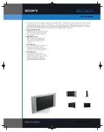
Before these panels can be accessed, the rear cover has to be
removed:
Figure 4-1
1.
Place the Display Box in the service stand via 2 reinforced
cushions (order code: 3122 126 30181).
2.
Remove the 9 fixation screws of the rear cover.
3.
Remove the rear cover (during removal push it slightly
upwards).
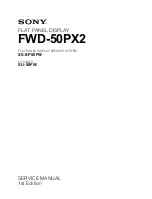
Figure 4-2
1.
All panels are now accessible.
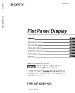
4.1.1
VS/VA SUPPLY panel.
Figure 4-3
1.
Disconnect Fan Supply cable from connector FD07 in the
upper left corner [1].
2.
Remove the 7 fixation screws of the panel [2].
3.
Place panel on the 2 hinges, which are located near the
right corners of the panel [3].
4.
Use the mechanical service part (extension cable
assembly, 12NC: 3122 785 90006) to extend the Fan
Supply cable [4].
5.
The copper side is now accessible from the left.
4.1.2
PDP DISCHARGE panel.
As in the FTV 1.5, this panel must be exchanged completely if
defective.
4.1.3
AUDIO AMPLIFIER panel.
Figure 4-4
CL 96532069_130.EPS
120899
2
1
CL 96532069_131.EPS
120899
VS/VA Supply
PDP Limesco
YUV/YC Input
PDP Discharge
Audio Amplifier
Pre-conditioner
AV Control
CL 96532069_132.EPS
120899
1
2
3
4
VS/VA Supply
FD07
CL 96532069_134.EPS
120899
2
2
3
1
Audio Amplifier
www.freeservicemanuals.info
3/2/2013
www.nostatatech.nl
World of free manuals