231E1 LCD
8
OSD Attention Signals
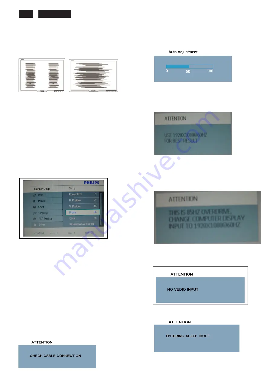
Clock & Phase Adjustment
Due to the different quality of video signal generated from
graphics cards. It is necessary to adjust CLOCK and PHASE
functions for the optimal video display of LCD monitor. So
maybe some flicker appeared as Fig.1 & 2.
Fig.1 Fig.2
Following steps will guide you to make correct adjustment of
CLOCK and PHASE:
a. Restart your computer.
b. Press
MENU
to bring up OSD menu after the OS
(Operation System) boot up.
c. Press
UP
or
DOWN
to select the option of
setup
and then press
MENU
to bring up its submenu as shown in
Fig.3.
d. Select the
Clock
or
Phase
adjustment items in submenu
and press
UP
or
DOWN
to adjust.
(If the phenomenon as Fig.1, you should adjust “
Phase
”)
(If the phenomenon as Fig.2, you should adjust “
Clock
”)
e. Quit OSD by press
MENU
button to save the settings.
Fig.3
However, CLOCK and PHASE functions are only available while
analog video signal is supplied. Operating unit under digital signal
state, the video clock information can be obtained from graphics
cards directly. So, it is unnecessary to adjust these functions.
OSD Attention signal
The monitor will detect various display situation automatically.
When the monitor detects the problems, the screen will show the
different warning signals to remind you what is happen to your
monitor.
1. CHECK CABLE CONNECTION
This screen appears if there is no video signal input. Please
check that the signal cable is properly connected to the video
card of PC and make sure PC is on.
2. AUTO ADJUSTMENT
This screen appears when you touch the
AUTO
button.
It will disappear when the monitor is properly adjusted.
3. USE 1920X1080@60HZ FOR BEST RESULT
This message appears when the video mode input is not
the recommended 1920*1080@ 60Hz. Other modes
may result in some picture distortion. Please adjust the
video mode to 1920*1080 @ 60Hz for best display
quality.
4. 85HZ OVERDRIVE MESSAGE
This message appears when the video mode input is
more than 85 HZ. The message “THIS IS 85HZ
OVERDRIVE,CHANGE COMPUTER DISPLAY INPUT TO
1920X1080@60HZ”
is warmed, around 5 seconds in each minutes, after 10
minutes will go into power saving mode.
5.
NO VIDEO
INPUT( ENTERING SLEEP MODE
If input VGA you are selecting is not signal input, following
message will appear on the screen.
After 5 s, the monitor will go into power saving mode,
following message will appear on the screen.
Please check that the signal available is properly
connected to the video card of PC and make sure PC is
on.
Summary of Contents for 231E1HSB
Page 12: ...231E1 LCD 12 Wiring diagram ME ...
Page 23: ...231E LCD 23 220EW9 LCD 23 Schematic Diagram Scaler Board Power ...
Page 24: ...231E1 LCD 24 Schematic Diagram VGA Input ...
Page 25: ...231E LCD 25 220EW9 LCD 25 Schematic Diagram DVI Input ...
Page 26: ...231E1 LCD 26 Schematic Diagram Scaler Board Scaler ...
Page 27: ...231E LCD 27 220EW9 LCD 27 Schematic Diagram Power Board ...
Page 28: ...231E1 LCD 28 Layout side View Scaler Board 1 ...
Page 30: ...231E1 LCD 30 Layout side View Power Board ...
Page 31: ...231E LCD 31 220EW9 LCD 31 Exploded View ...
Page 39: ...231E LCD 39 General Trouble Shooting Guide ...
Page 41: ...231E LCD 41 General Trouble Shooting Guide Continued 1 ...
Page 43: ...231E LCD 43 General Trouble Shooting Guide ...
Page 44: ...231E1 LCD 44 General Trouble Shooting Guide 5 ...
Page 45: ...231E LCD 45 General Trouble Shooting Guide 6 ...
Page 46: ...231E1 LCD 46 General Trouble Shooting Guide 7 ...
Page 47: ...231E LCD 47 General Trouble Shooting Guide 8 ...
Page 48: ...231E1 LCD 48 General Trouble Shooting Guide 9 ...
Page 49: ...231E LCD 49 General Trouble Shooting Guide 10 ...
Page 50: ...231E1 LCD 50 General Trouble Shooting Guide 11 ...
Page 51: ...231E LCD 51 General Trouble Shooting Guide 12 ...
Page 52: ...231E1 LCD 52 General Trouble Shooting Guide 13 ...
Page 69: ...231E LCD 69 END ...


