231E LCD
7
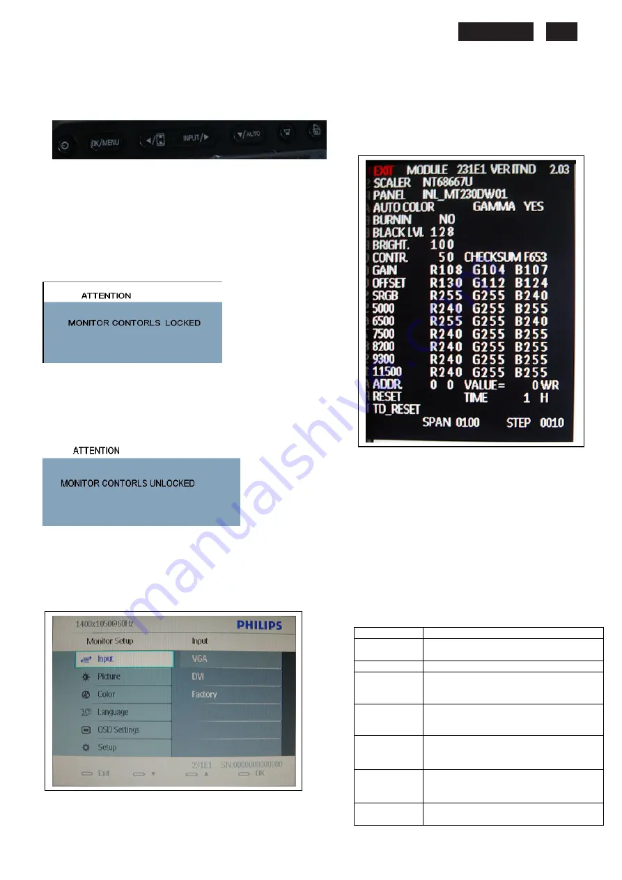
Advanced OSD Adjustment
(FW)
Advanced OSD Adjustment
1. Front control panel
`
2. To Lock/Unlock OSD function
The OSD function can be locked by pressing
MENU
button
for more than 6 seconds, the screen shows following windows for
5 seconds.
Every time when you press any button, this message
appears on the screen automatically.
Locked OSD function can be released by pressing
MENU
button for more than 6 seconds. While press
MENU
button
for OSD unlocked purpose, the screen will keep showing OSD
MAIN MENU LOCKED until OSD function unlocked and
screen automatically shows following window for 5 seconds.
3. Access Factory Mode
Press
POWER
button to Power off, then Press
AUTO
+
MENU
at the same time, and then press [
POWER
] for DC power on.
OSD menu will be shown with “Factory” on the sub –menu of
Input.. Select “Factory” for entering factory mode.
If this message appeared, means monitor already entered
the factory mode.
4. Entering Burn-in mode and others
If you access into factory mode, press
MENU,
Select Input-Factory,
then press
MENU
to confirm,
OSD menu willconvert into another format as below:
Move the cursor by
MENU
button, and press the
UP
or
DOWN
button to change the burn-in mode from On to
Off.
Leave factory mode by simply power off(DC off) the
monitor.
Warming:
* If you only want to enter burn in mode, please don’t
change
any other setting items as above listed.
Appendix:
Explanation of above listed selections.
Selection
Description
Burn in
On/Off
Enter Aging Mode
Auto Color
Auto Color Adjustment
Gain
ADC Gain Value Adjustment
(Auto adjustment by H/W when
implement Auto Color function)
Offset
ADC Offset Value Adjustment
(Auto adjustment by H/W when
implement Auto Color function)
9300K
9300K Color Temperature Gain Value
Adjustment
6500K
6500K Color Temperature Gain Value
Adjustment
Reset
Memory Racall To Factory Default
Settings
Summary of Contents for 231E1HSB
Page 12: ...231E1 LCD 12 Wiring diagram ME ...
Page 23: ...231E LCD 23 220EW9 LCD 23 Schematic Diagram Scaler Board Power ...
Page 24: ...231E1 LCD 24 Schematic Diagram VGA Input ...
Page 25: ...231E LCD 25 220EW9 LCD 25 Schematic Diagram DVI Input ...
Page 26: ...231E1 LCD 26 Schematic Diagram Scaler Board Scaler ...
Page 27: ...231E LCD 27 220EW9 LCD 27 Schematic Diagram Power Board ...
Page 28: ...231E1 LCD 28 Layout side View Scaler Board 1 ...
Page 30: ...231E1 LCD 30 Layout side View Power Board ...
Page 31: ...231E LCD 31 220EW9 LCD 31 Exploded View ...
Page 39: ...231E LCD 39 General Trouble Shooting Guide ...
Page 41: ...231E LCD 41 General Trouble Shooting Guide Continued 1 ...
Page 43: ...231E LCD 43 General Trouble Shooting Guide ...
Page 44: ...231E1 LCD 44 General Trouble Shooting Guide 5 ...
Page 45: ...231E LCD 45 General Trouble Shooting Guide 6 ...
Page 46: ...231E1 LCD 46 General Trouble Shooting Guide 7 ...
Page 47: ...231E LCD 47 General Trouble Shooting Guide 8 ...
Page 48: ...231E1 LCD 48 General Trouble Shooting Guide 9 ...
Page 49: ...231E LCD 49 General Trouble Shooting Guide 10 ...
Page 50: ...231E1 LCD 50 General Trouble Shooting Guide 11 ...
Page 51: ...231E LCD 51 General Trouble Shooting Guide 12 ...
Page 52: ...231E1 LCD 52 General Trouble Shooting Guide 13 ...
Page 69: ...231E LCD 69 END ...


