DDC Instructions
22
202P4 M25P
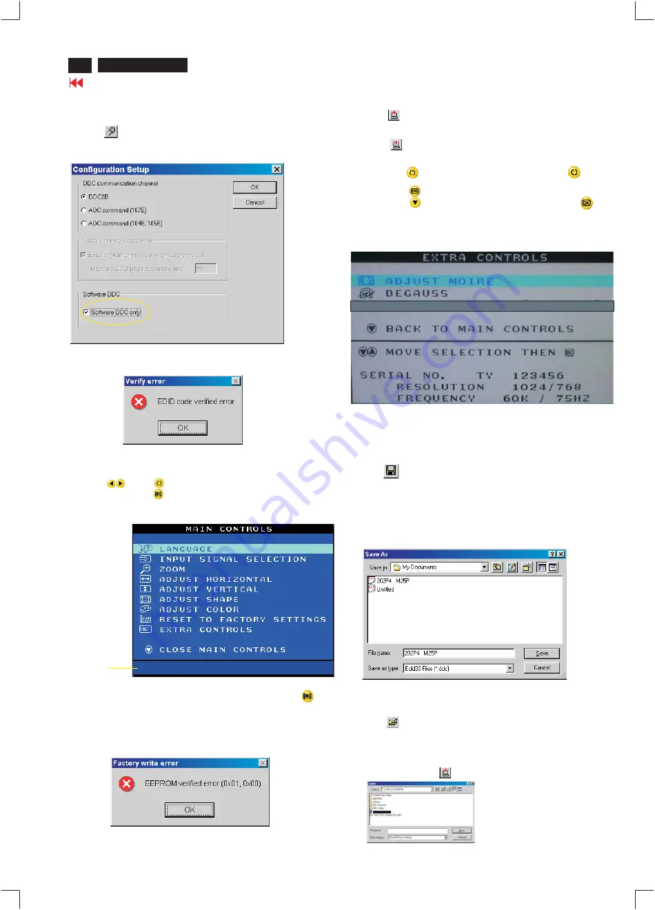
Fig. 16
Fig. 18
Step 8: Save DDC data
Sometimes, you may need to save DDC data as a text file for using
in other IC chip. To save DDC data, follow the steps below:
1. Click
(Save) icon (or click "file"-> "save as") from the tool bar
and give a file name as shown in Fig. 19.
The file type is EDID301 file (*.ddc) which can be open in WordPad.
By using WordPad, the texts of DDC data & table (128 bytes, hex
code) can be modified. If DDC TEXTS & HEX Table are completely
correct, it can be saved as .ddc flie to re-load it into EEPROM for
DDC Data application.
Step 5: **Configuration Setup & Enter Factory Mode **
for "write EDID data"
1.
Click
icon from the tool bar to bring up the Configuration Setup
windows again. Then, select "Software DDC only" as shown in
Fig. 16. Click "OK".
Step 6: Write DDC data
1.
Click
(Write EDID) icon from the tool bar to write DDC data.
Bring up "Writing 0%~100%, ready" a progressing bar on the left
down corner.
2.
Click
(Read EDID) to confirm it.
Step 7: Confirm Serial Number in User Mode
1
.
Press the
button to turn off the monitor. Press the
button
again to turn on the monitor.
2.
Press the
button to bring up the OSD Main Menu.
3.
Press the
button to select Extra Controls, press the
button to confirm your selection.
4.
Confirm the Serial Number "123456" is updated
as shown in Fig. 18.
Fig. 19
If you do not select "Software DDC only", when you execute
"write EDID", it will bring up an error message as below.
If you do not access "Factory mode", when you execute
"write EDID", it will bring up an error message as below.
To access factory mode
1. Turn off monitor (don't turn off PC)
2. Press "
" and "
" simultaneously on the front control
panel,then press "
",wait till the OSD menu with characters
CM25 PLUS V0.55 20011128 (below OSD menu)" come on the
screen of monitor.
If OSD menu disappears on the screen of monitor, press "
"
again (anytime), then the OSD menu comes on the screen again.
Fig. 17
MODEL SELECT
CM25
PLUS
V0.55
20011128
Factory
Mode
Indicator
------------->
2.
Click
.
Save
Fig. 20
Step 9: Load DDC data
Open
1.
Click
from the tool bar.
2.
Select the file you want to open as shown in Fig. 20.
3.
Click
.
4.
Access "Factory Mode" and enable "Software DDC only" as shown
in Fig. 17 & Fig. 16.
5.
Write EDID (click
).
202P4 M25P
202P4 M25P
1
1
Summary of Contents for 202P4
Page 31: ...Terminal Schematic Diagram A1 Go to cover page ...
Page 33: ......
Page 34: ......
Page 35: ...Go to cover page ...
Page 37: ...Key Control Schematic Diagram 202P4 M25P 32 34 Go to cover page E ...
Page 39: ...Go to cover page ...
Page 41: ......
Page 43: ...Power Schematic Diagram C C1 C6 C2 C7 C3 C4 C5 C9 C8 Go to cover page ...
Page 45: ...Drive Schematic Diagram 202P4 M25P 32 38 D Go to cover page ...
Page 91: ...83 202P4 M25P Repair Flow Chart Go to cover page 7 0 2 ...


