


Microstep Resolution
The microstep resolution of the FSC-01 is set by the PHD Programmer software.
Make sure the step resolution of the FSC-01 is the same as the servo drive it is connected to.
Consult the PHD Quick Start Manual for additional information (part #6441-334).
Connecting the Step and Direction
Outputs
The FSC-01 Motion Controller can work with most pulse and direction step motors or servo drives.
Different step motor drives use different input configurations. There are three basic types that the
FSC-01 can be used with:
• Differential: Driver has STEP+, STEP-, DIR+, and DIR- inputs. Many high speed
microstep drivers use differential inputs.
• Common anode: Driver has STEP and DIR inputs that require sinking signals
and a common terminal named “VOPTO” or “+5V”
• Common cathode: Driver inputs are STEP and DIR (requiring sourcing signals)
and a common terminal named “common” or “ground.”
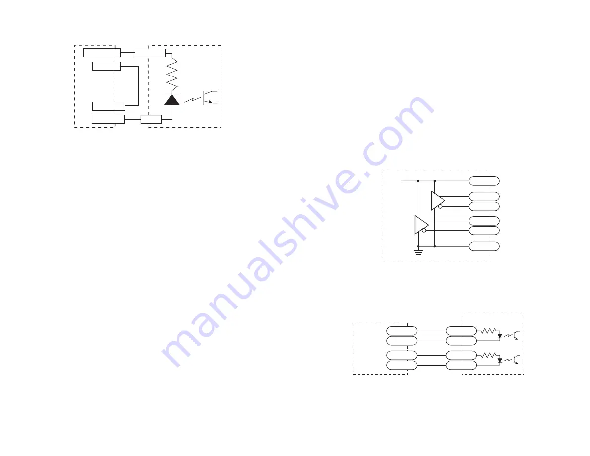
Wiring diagrams for each type of driver are shown below and on the next page. The first sketch
shows the output circuits for the FSC-01.
FSC-01
STEP+
STEP–
DIR+
DIR–
Driver
STEP+
STEP–
DIR+
DIR–
Connecting to a Driver with Differential Inputs
FSC-01 Step & Direction Output Circuit
inside
FSC-01
26C31
+5 VDC
GND
STEP+
STEP–
DIR+
DIR–
+5V
-14-
-7-
Continued from previous page.
Note: Please consult the PHD Quickstart Manual (part number #6441-334) for
connection details.
(Note: Power supply may be built into PLC and internally wired to the common)
Typical diagram for interfacing an FSC-01 output to an PNP type PLC input.
OUTPUT -
COMMON
INPUT
FSC-01
Motion
Controller
+ 24 VDC
24 VDC GND
PLC With
PNP Input