background image

AxN Configurable Motion Control Platform


12 


2.1


Specifications 

Specifications 

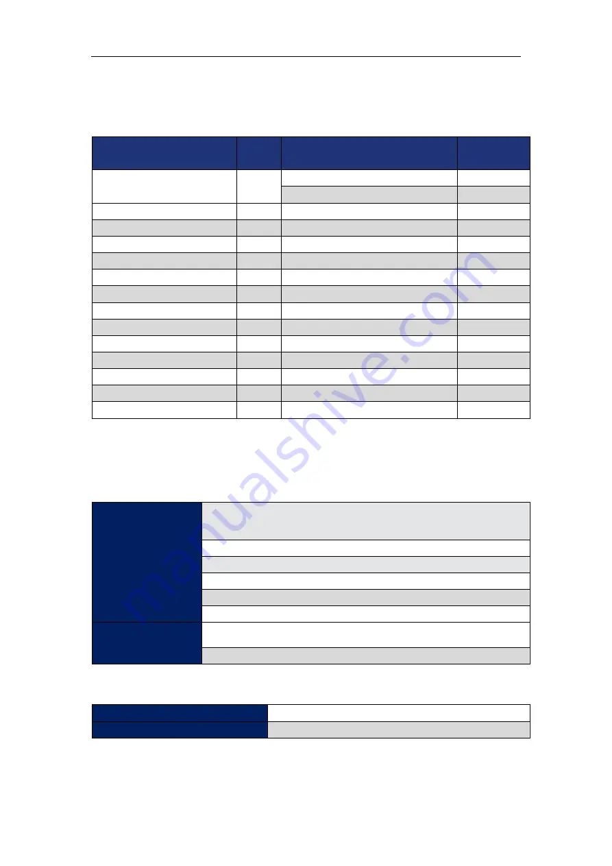
Technical specifications


Symbol


AxN 09.20.4


Units


Power Supply Voltage 

𝑽

𝑖𝑛


150 ~ 500 

Vac 3 phase 

0 ~ 800 

Vdc 

Auxiliary supply voltage 

𝑽

𝑎𝑢𝑥


24V ± 15% / 2A 

Vdc 

Output frequency 

𝒇


0 ~ 1200 

Hz 

Current output, S1

(1)


𝑰

𝑜


Arms 

Peak current

(1)


𝑰

𝑝


20 

Arms 

Power Losses total

(2)


𝑷

𝑙


200 

Maximum output voltage   

𝑽

𝑜𝑢𝑡


𝑽

𝑖𝑛

× 0.95


Vac 

PWM frequency

(3) 

𝒇

𝑝𝑤𝑚


4 / 8 / 16 

kHz 

Efficiency at nominal power

(1)


-- 

97.9 

Input form factor (Full load) 

-- 

0.9 

Vac 3 phase 

Maximum braking current 

-- 

100% of 

𝑰

𝑝

  (peak current) 

-- 

Cooling 

-- 

1 fan 40

 × 

40

 ×  20


-- 

Flow rate 

-- 

25.2 

m

3

/hour


Dimensions (H

×

W

×

D) 

-- 

201.8

×

96

×

164.6 

mm 

(1)

 𝑽

𝑖𝑛

  = 380 Vac, 

𝑽

𝑜𝑢𝑡

= 𝑽

𝑖𝑛

× 0.95,  𝐓

𝑎𝑚𝑏

  = 40

, Comm.Freq.8kHz 

(2) Including input rectifier losses 
(3) PWM frequency will automatically decrease at Zero Speed, in order to keep Nominal Current Output 

Motor Feedback Options 

Main Encoder 
(500kHz) 

Sincos encoder 5 channels (2 absolute analog tracks/2 incremental 
analog tracks/index) 

Incremental encoder (1 Vpp or Different Line Driver) 

Sensorless algorithm (w/o feedback) 

Endat serial encoder 1.0 to 2.2 (default) 

Resolver 

Hiperface encoder 

Secondary Encoder 
(500kHz) 

Incremental digital encoder without commutation tracks (500kHz) 

Endat serial encoder 

Programmable Input Signals 

2 Differential analog inputs 

± 10V (1mV) / R

in

 = 10kΩ 

8 digital inputs 

20 ~ 30V / R

in

 = 6.6kΩ to GND 

Programmable Output Signals 

Summary of Contents for AxN

Page 1: ......

Page 2: ...upply Input 26 4 2 5 Brake Resistor 28 4 2 6 Motor Power Output Port P2 30 4 2 7 Motor Power Output 31 4 3 Control Circuit 33 4 3 1 Auxiliary Power Supply AUX Power 33 4 3 2 Safe Torque Off STO 34 4 3...

Page 3: ...AxN Configurable Motion Control Platform 2 1 SAFETY INSTRUCTIONS READ FIRST AxN Configurable Motion Control Platform Powered by Phase Motion Control...

Page 4: ...al changes are permitted It is not permitted to decompile software products or alter source codes Do not mount damaged or faulty products or use them in operation Make sure that the products have been...

Page 5: ...em on to Others Do not attempt to install or commission this device without first reading all documentation provided with the product Read and understand these safety instructions and all user documen...

Page 6: ...given in the documentation of the product with regard to the use of the delivered components contains only examples of applications and suggestions The machine and installation manufacturer must make...

Page 7: ...ponent Risk of injury by improper handling Risk of bodily injury by bruising shearing cutting hitting or improper handling of pressurized lines 1 3 Instructions with regard to Specific Dangers Protect...

Page 8: ...r r c d cannot be used for electric drives Indirect contact must be prevented by other means for example by an overcurrent protective device according to the relevant standards Secure built in devices...

Page 9: ...y the danger of bodily harm and material damage this alone cannot be relied upon to ensure complete safety Until the integrated monitoring functions become effective it must be assumed in any case tha...

Page 10: ...of normal use before initial startup If necessary perform a special electromagnetic compatibility EMC test on the installation Protection against Magnetic and Electromagnetic Fields during Operation...

Page 11: ...tive safety regulations has to take measures to avoid injuries caused by burns in the end application These measures can be for example warnings guards shielding or barrier and technical documentation...

Page 12: ...AxN Configurable Motion Control Platform 11 2 TECHNICAL SPECIFICATIONS AxN Configurable Motion Control Platform Powered by Phase Motion Control...

Page 13: ...2 m3 hour Dimensions H W D 201 8 96 164 6 mm 1 380 Vac 0 95 40 Comm Freq 8kHz 2 Including input rectifier losses 3 PWM frequency will automatically decrease at Zero Speed in order to keep Nominal Cur...

Page 14: ...figuration Processor speed 80 MIPS C FPGA 120 MIPS C FPGA Extreme Version Optional Task frequency Current drive monitoring 1 MHz Position speed loop 8 kHz PLC fast task 8 kHz PLC slow task 15 625 Hz t...

Page 15: ...to 1000m above MSL over 1000m above MSL with power reduction 1 per 100m up Pollution Severity 2 Installation Type Built in unit only for vertical installation in a switch cabinet with min IP4x protec...

Page 16: ...d in the table must not occur simultaneously 3 The absolute humidity is limited to max 25 g m That means that the maximum values for temperature and relative air humidity stipulated in the table must...

Page 17: ...AxN Configurable Motion Control Platform 16 3 MECHANICAL INSTALLATION AxN Configurable Motion Control Platform Powered by Phase Motion Control...

Page 18: ...to the drive Place a temporary cover over the top of the drive during installation Remove the temporary cover before start up as the cover will reduce ventilation and cause the drive to overheat 4 In...

Page 19: ...lorides Altitude Up to 1000m above MSL over 1000m above MSL with power reduction 1 per 100m up Vibration Amplitude up to 0 3mm at 2 to 9 Hz Acceleration up to 1m s2 at 9 to 200 Hz Orientation Install...

Page 20: ...n To maintain proper cooling install the AxN drive upright inside the switch cabinet as illustrated below WARNING The airflow inside the drive must be upright after installation as illustrated below I...

Page 21: ...or air out B 10mm The distance between other device including other AxN drives and peripheral devices C 30mm The distance between the inside wall of the switch cabinet D 100mm The distance between the...

Page 22: ...AxN Configurable Motion Control Platform 21 4 ELECTRICAL INSTALLATION AxN Configurable Motion Control Platform Powered by Phase Motion Control...

Page 23: ...to four single ended signal Analog signal reference GND U1 3 U2 16 U2 17 AO0 AO1 Analog outputs programmable 0V U1 12 0V U2 24 Digital signal reference GND Digital signal reference GND 0V U1 12 Digit...

Page 24: ...supply AT THE SAME TIME Refer to the following figures for standard drive connection diagram NOTE the input and output ports in the following figures do not represent the true location on the drive p...

Page 25: ...port has different functions by using different combinations of terminals Refer to following table for more details Function Terminal Definition Description AC Power Supply Input T Three phase AC pow...

Page 26: ...tween the cable and drive R S T terminals of AxN 09 20 4 drive are recommended to use the E Series Cord End Terminals manufactured by KST And PE terminal is recommended to use the RNY Series Ring Term...

Page 27: ...the nominal torque to tight these terminals is 0 5 0 6 N m AC Power Supply Cable Installation 4 2 4 DC Power Supply Input DC Power Supply Requirement Main Supply AxN 09 20 4 Voltage 565V Type DC powe...

Page 28: ...ow lists the appropriate terminal Recommended Pre insulated Crimp Terminals Recommended Strip Length mm AxN 09 20 4 E2508 phase wire RNYBS22 6 ground wire 10 Cable Shield Grounding Wiring the cable sh...

Page 29: ...ve has an internal brake resistor inside the drive And it can also connect an external brake resistor Recommended WARNING Do not operate AxN Drive without any brake resistor Failure to comply may resu...

Page 30: ...bort because of the high DC Bus Voltage over 900V Refer to following table to check the Minimum and Maximum Resistance of external brake resistor Minimum Resistance Maximum Resistance AxN 09 20 4 19 3...

Page 31: ...6 Motor Power Output Port P2 AxN 09 20 4 Drive s Motor Power Output Port P2 has one function output power to the motor Port Location AxN 09 20 4 Drive s Motor Power Output Port P2 is on the bottom of...

Page 32: ...tor Power Output cable The table below lists the appropriate cable Current Arms Cross sectional Area mm2 AWG AxN 09 20 4 9 4 17 11 Pre insulated Crimp Terminals Crimping pre insulated Terminals on the...

Page 33: ...g and Torque Specification Connect the 4 wires of the motor power cable to the correspond terminals on the P2 port U to A V to B W to C and PE to PE Cable Fixing Use a hose clamp to fix the cable on t...

Page 34: ...V Type DC power Fluctuation of Voltage 15 22 8 25 2V Nominal Power 48W Nominal Current 2A Port Location AxN 09 20 4 Drive s Auxiliary Power Supply Port Female Plug 4Pin is on the top of the drive And...

Page 35: ...4 Drive Normal version AxN 09 20 4 Drive has already internally short cut Pin 24V_AUX 24_SAF_H and 24V_SAF_L so that STO function is disabled STO Function Enable The STO function is implemented using...

Page 36: ...lay R1 Port Location AxN 09 20 4 Drive s System Relay Port Female Plug 3Pin is on the top of the drive And a corresponding System Relay Terminal Male Plug 3Pin is provided in the accessories Refer to...

Page 37: ...normally closed contact Diagram AxN 09 20 4 Drive uses a relay to indicate the status When Drive is power off or system is not ready the circuit is connected between N C Normally Closed and Com In the...

Page 38: ...E1 Encoder Connector SinCos Endat Digital Incremental with Hall Resolver and Hiperface U1 U2 User Connectors 4 Analog Inputs 2 Analog Outputs 8 Digital Inputs 4 Digital Outputs S1 Serial Bus Connecto...

Page 39: ...Hall Resolver and Hiperface Encoder Different position sensor has different pin assignment refer to correspond section for more details If the motor is manufactured by Phase Motion Control our Prefab...

Page 40: ...ntial 6 Vcc Encoder supply 5Vdc Positive supply voltage 7 A Encoder incremental channel 1 Vpp differential 8 KTY Thermal sensor positive 9 I Encoder index 1 Vpp differential 10 11 12 A Encoder increme...

Page 41: ...CK Endat clock TTL 4 CLOCK Endat clock TTL 5 6 Vcc Encoder supply 8Vdc Positive supply voltage 7 8 KTY Thermal sensor positive 9 DATA Endat data TTL 10 11 12 13 14 DATA Endat data TTL 15 Connection Ta...

Page 42: ...Encoder supply 8Vdc Positive supply voltage 7 B Encoder incremental channel TTL 8 KTY Thermal sensor positive 9 I Encoder index TTL 10 11 12 B Encoder incremental channel TTL 13 A Encoder incremental...

Page 43: ...OS Absolute channel Differential signal 5 SIN Absolute channel Differential signal 6 7 8 KTY Thermal sensor positive 9 10 RESEX Resolver energising 8kHz sinusoidal wave 11 RESEX Resolver energising 8k...

Page 44: ...ge 7 COS Process data channel TTL 8 KTY Thermal sensor positive 9 DATA RS 485 parameter channel TTL 10 11 12 COS Process data channel TTL 13 SIN Process data channel TTL 14 DATA RS 485 parameter chann...

Page 45: ...4 9 RS 232 Pin Assignment Pin Standard RS 232 AxN RS 232 Function 1 DCD Data Carrier Detect 2 RXD RXD Received Data 3 TXD TXD Transmitted Data 4 DTR DTR Data Terminal Ready 5 GND GND Common Ground 6...

Page 46: ...ing only of transmit data receive data and ground is commonly used when the full facilities of RS 232 are not required And it is also the minimal connection requirement of Cockpit communication with A...

Page 47: ...connection is the maximal connection which AxN 09 20 4 drive can support NOTE Do NOT use 9 wire connection AxN 09 20 4 drive does not support DCD and RI function Connection table 1 N C No Connection...

Page 48: ...GND GND Ground 6 7 8 9 RS 422 Connection Table RS 485 Connection Table 1 N C No Connection 2 Connector back shell shielded 360 Both ends 3 means that the shield or cable should connect to connectors S...

Page 49: ...o the S1 connector Pin Assignment Pin CANOpen Function 1 CAN_H CAN_H bus line dominant high 2 3 4 5 GND Ground connection 6 7 8 9 CAN_L CAN_L bus line dominant low Note CANOpen pin assignment on S1 co...

Page 50: ...AxN Configurable Motion Control Platform 49 Connection diagram Note Only the first and the last CAN node device should use a 120 terminal resistor...

Page 51: ...t Port Location AxN 09 20 4 Drive s Main CAN Port Female Plug 9 Pin D Sub is on the middle side of drive s communication port panel Refer to the following figures for exact location 4 4 13 Main CAN Ax...

Page 52: ...nnection Table 1 N C No Connection 2 Connector back shell shielded 360 Both ends 3 means that the shield or cable should connect to connectors Connection diagram Note Only the first and the last CAN n...

Page 53: ...f Simulated Incremental Encoder is 0 3 3V Endat Encoder IN Pin Name Function 1 DATA Endat Data 2 3 GND Ground connection 4 CLOCK Endat Clock 5 6 DATA Endat Data 7 8 CLOCK Endat Clock 9 Incremental Enc...

Page 54: ...CAT network through two connectors EtherCAT IN and EtherCAT OUT Port Location AxN 09 20 4 Drive s EtherCAT Port is on the upside of drive s communication port panel formed by two RJ45 100Base TX femal...

Page 55: ...Location AxN 09 20 4 Drive s User Connectors Male Plug 2 12 pin are on the left bottom of the Communication Port Panel Refer to the following figure for exact location Diagram NOTE All analog signal...

Page 56: ...switch between differential mode and single end mode 1 15 R1N AI3 Programmable analog input 10V Zin 10K able to switch between differential mode and single end mode 1 16 AO1 Programmable analog output...

Page 57: ...AxN Configurable Motion Control Platform 56 5 APPENDIX ACCESSORIES AxN Configurable Motion Control Platform Powered by Phase Motion Control...

Page 58: ...4 4 4mm B04 4 4mm 2 __mm D06 4 6mm B06 4 6mm 2 __mm D10 4 10mm B10 4 10mm 2 __mm D16 4 16mm B16 4 16mm 2 __mm D25 4 25mm B25 4 25mm 2 __mm Length 3 3m 5 5m 7 7m X 2 X m Shield Type G General shielded...

Page 59: ...ncremental with Hall sensor Terminal Type X Aviation plug DB15 180 outlet Y Aviation plug DB15 45 outlet Wire Gauge 1 A28 AWG28 Length 3 3m 5 5m 7 7m X 2 X m Shield Type G General shielded I General I...

Page 60: ...etal plate can ensure that the cable shield is effectively grounded and the grounding impedance is reduced Installation Put the open holes of cable support together with the ports of the drive located...

Reviews: