22 |
P a g e
radio signals or sensitive electronic equipment near the installation. The use of shielded cables and
rigid metal conduit on the output lines between the drive and the motor is recommended to reduce EMI.
When it is not practical to use continuous metal conduit, shielded cables can be used. The shielded
cable should be constructed with symmetrical conductors and a copper or aluminum shield covered with
an insulating jacket. A good shield results in lower EMI and lower motor bearing currents.
Routing Power Cables
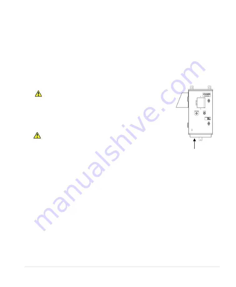
Power cables should enter only through the bottom of the drive enclosure directly beneath the power
terminals. Enclosures are supplied with conduit openings. Do not install line-side power cables in the
same conduit or cable tray with load side power cables. Also, do not route control cables through the
same conduit or cable tray as power cables.
Figure 20 -
Routing Power Cables
Routing Control Cables
A separate conduit for control cables should be used. This reduces the exposure of control cables to
EMI in the motor cables. Conduit openings are provided in the enclosure. If the control cables must
intersect the power cables, make sure they cross at right angles.
Output Filters
Some installations may require a sine wave filter between the drive and the motor. A filter reduces
harmonics in the PWM output voltage, smoothing the waveforms to reduce vibration in the motor.
Filters also reduce common mode currents in the motor windings that can discharge through motor
bearings, causing pitting and premature motor failure. See
Section 2.1
Model Nomenclature
, for
recommended filter for each model.
CAUTION:
Avoid routing
control cables and power cables in
close proximity to avoid coupling
EMI onto control cables.
Conduit openings for power and control cables are located in the bottom
of the enclosure.
WARNING:
Do not create conduit openings in other locations on
the enclosure. This may damage the drive and void the warranty.
Summary of Contents for 2XD Series
Page 10: ...4 P a g e 2 3 Dimensional Drawings Figure 5 SD Series Line Drawing...
Page 11: ...5 P a g e Figure 6 SD Series Line Drawing if selected with optional breaker see Figure 9...
Page 12: ...6 P a g e Figure 7 SD Series Line Drawing if selected with optional breaker see Figure 9...
Page 14: ...8 P a g e Figure 9 SD Series Line Drawing...
Page 15: ...9 P a g e Figure 10 SD Series Line Drawing...
Page 16: ...10 P a g e Figure 11 2XD Series Line Drawing...


