background image

30198-004b 5 

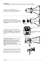
2. Mounting  

We recommend making the electrical connection at the base before assembling the device. 

2.1 Release fixing screws from the horn.  

Caution

: The two fixing square nuts inside the horn are 

not fixed in place. Hold them in place when removing the 
screws. 

2.2 Remove the horn. 
Fix the driver system to the horn. Position the driver 
so that in fully mounted state, the sounder bleed hole 
faces downwards. For this purpose, use the distance 
washer included in the accessories kit. 


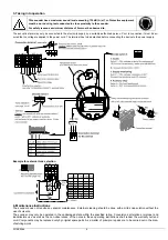
2.3 Electrical connection (see also page 6).


Following electrical installation, connect the cable 
from the pcb to the + or - connection on the driver 
(see fig.). Also connect the temperature sensor to the 
center of the driver with the adhesive strip included in 
the accessories kit.


Finally, connect the housing and horn with the previ-
ously removed screws.  
Do not forget the O-ring between the horn and the 
housing. 
Caution: In certain cases, condensate may form in-
side the sounder. For this reason, ensure that one of 
the two bleed screws (A or B) has been removed and 
that the opening faces downwards.  
Make sure that both bleed holes (in the housing and 
in the driver) face downwards.


For fixing, the supplied bracket or the pole bracket 
(available as option) may be used. 
Outdoor installation: The horn opening must not point 
upwards following installation of the sounder.


Summary of Contents for PA 130

Page 1: ...nach Konfiguration auch f r die Meldung einer St rung des Schallgebers verwendet werden Optional ist die Steuerung des Schallgebers ber ein RS485 Netzwerk m glich 1 Technische Daten Nennspannung 230V...

Page 2: ...on der Platine kommenden Kabel mit dem bzw Anschluss des Treibers siehe Bild Befestigen Sie au erdem den Temperatursensor mit dem im Beipack befindlichen Klebe streifen auf der Mitte des Treibers Absc...

Page 3: ...ektrischen Anschluss muss die Klemme abgenommen werden Beispiel f r externe Tonartenanwahl 4 Wartungshinweise Der Schallgeber erfordert keine besondere Wartung Die u ere Reinigung sollte mit einer sch...

Page 4: ...te a fault in the sounder Optionally the sounder may be controlled via an RS485 network 1 Technical data Rated voltage 230V AC 24 48V DC Frequency 50 60Hz Voltage range 25 15 20 60 V DC Current consum...

Page 5: ...ect the cable from the pcb to the or connection on the driver see fig Also connect the temperature sensor to the center of the driver with the adhesive strip included in the accessories kit Finally co...

Page 6: ...o be detached before connecting the device to the power supply Example for external tone selection 6 Maintenance Instructions The sounder does not require any special maintenance External cleaning sho...

Page 7: ...e peut tre utilis e galement pour signaler une panne de la sir ne La commande de la sir ne est possible en option via un r seau RS485 1 Caract ristiques techniques Tension d alimentation 230 V CA 24 4...

Page 8: ...fournies Pour finir fixez le bo tier et le pavillon avec les vis d mont es pr c demment Ne pas oublier le joint torique entre le pavillon et le bo tier Attention il est possible dans certains cas que...

Page 9: ...e raccordement lectrique la borne doit tre retir e Exemple pour s lection externe des sons 4 Notices d entretien La sir ne ne n cessite aucun entretien particulier Il est recommand de proc der au nett...

Page 10: ...essere utiliz zata anche per la segnalazione di malfunzionamento della sirena 1 Specifiche tecniche Tensione nominale 230 V CA 24 48 V CC Frequenza nominale 50 60 Hz Campo di funzionamento 25 15 20 60...

Page 11: ...iuto dell adesivo incluso nel kit di accessori A continuazione collegare l alloggiamento e la tromba con le viti rimosse in precedenza Non dimenticare l O Ring fra tromba ed alloggiamento Attenzione P...

Page 12: ...nnet tore di alimentazione Esempio per selezione esterna dei suoni 4 Manutenzione La sirena non necessita di una particolare manutenzione Per la pulizia esterna utilizzare un detergente neutro senza s...

Page 13: ...N ON 9 15 53 2 52 Audio 10 ON ON ON ON 10 7 5 Audio 11 ON ON ON ON 11 2 51 5 54 Audio 53 12 ON ON ON 12 4 5 Audio 13 ON ON ON ON 13 15 5 Audio 14 ON ON ON 14 4 5 Audio 15 ON ON ON 15 2 77 5 59 Audio 7...

Page 14: ...ON ON ON 58 74 52 66 53 62 51 54 42 ON ON ON 59 75 51 64 53 55 51 54 43 ON ON ON 60 76 77 50 59 77 54 76 44 ON ON 61 77 51 73 67 69 63 59 45 ON ON ON 62 78 77 60 59 54 57 76 46 ON ON 63 79 51 80 55 5...

Page 15: ...signal signal danger r p titif descendant DIN 33404 T3 52 Notsignal f R umung audible emergency evacua tion signal Signal international d vacuation selon norme ISO 8021 53 Wechselton Alternating tone...

Page 16: ...101 We reserve the right to make any technical alterations in the interests of improvement Service pfannenberg com Nous nous r servons le droit de modifier certaines des caract ristiques ci dessus sel...

Reviews: