


Adjustment
13 - 24
13
.06.02
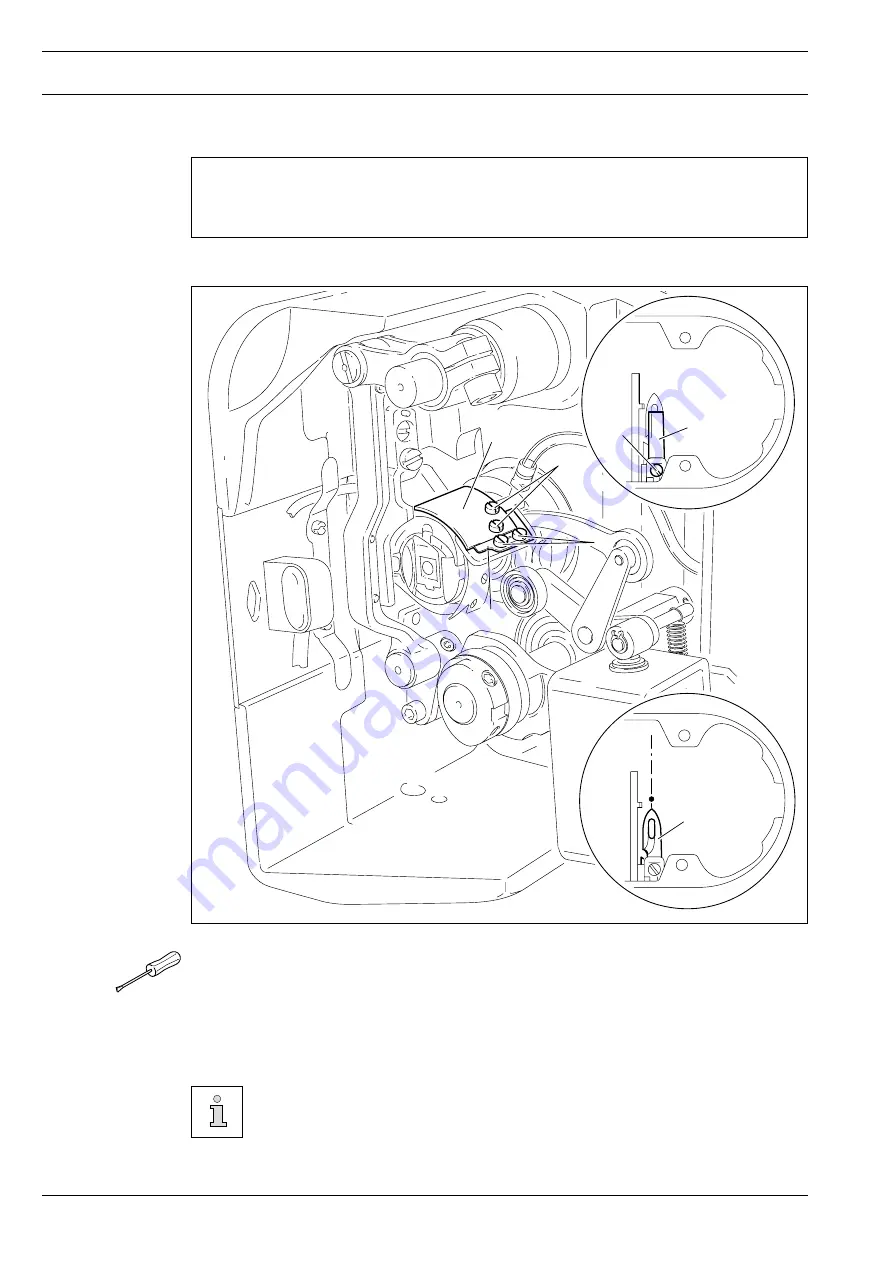
Lateral alignment of the thread catcher
Requirement
1. The tip of the thread catcher
5
must point exactly to the center of the needle.
2. The thread catcher
5
must be horizontal. It must not graze anything when it is operating.
●
Remove knife
1
(screw
2
).
●
Move needle bar to its BDC.
●
Loosen stop
3
(screws
4
).
●
Position thread catcher
5
(screw
6
) manually in front of the needle.
●
Align thread catcher
5
(screws
7
) according to the
requirements.
For further adjustments, leave knife
1
removed and stop
3
loosened.
Fig. 13 - 22
6
5
3
1
2
5
6
Summary of Contents for 2481-980/30 PLUSLINE
Page 106: ...15 2 View Version 27 01 03...
Page 107: ...15 3 91 191 441 95 Part 1 Version 24 01 02 Circuit diagram...
Page 108: ...15 4 Circuit diagram Version 24 01 02 91 191 441 95 Part 2...
Page 109: ...15 5 91 191 441 95 Part 3 Version 24 01 02 Circuit diagram...
Page 110: ...15 6 Circuit diagram Version 24 01 02 91 191 441 95 Part 4...
Page 111: ...Note...