V
IDBLOX
3G-SL
AND
3G-NE
RX
M
ODULE
Publication 81-9059-0667-0, Rev. C
March 2011
Proprietary Information of PESA
3-1
Chapter 3 Installation
3.1
G
ENERAL
I
NSTALLATION
C
ONSIDERATIONS
Vidblox 3G-SL and 3G-NE RX modules are shipped from the factory pre-configured to default
operating parameters, and in most installations, no further configuration should be required. There are
very few restrictions on placement of modules. Locate each module for convenient access to video
source signals or destination points. Ensure that a source of primary power is available and that each
module or extender frame has clearance for cooling air. It is not necessary that RX modules be
continuously connected to the facility Ethernet or to a host PC for operation. Vidblox 3G-SL modules
that are network connected may be monitored and controlled through a host PC running PESA’s Cattrax
network software control application. Monitoring and configuration functions may be performed on a
single module over a USB connection to a host PC running the Cattrax Cub controller application.
3.2
I
NSTALLING
V
IDBLOX
R
ECEIVER
M
ODULES
Receiver modules accept up to four (3G-SL), or two (3G-NE) inputs of SMPTE compliant 1080p (3G-
NE and 3G-SL), 720p (3G-SL Only) or 1080i (3G-SL Only) SDI video through chassis mounted BNC
connectors and, if equipped, the SFP fiber receiver channels. A video output in a user-selectable DVI-D
or analog format at a user-selectable resolution up to 1920x1200 is available at the chassis mounted
DVI-I connector. An unbalanced output of dual channel analog audio de-embedded from audio
channels 1 and 2 of SDI audio group 1 is available through the 3.5mm connector. Vidblox receiver
module inputs may be directly connected to Vidblox transmitter modules when used as media extenders,
or to the SDI output signal from a router or video processing device
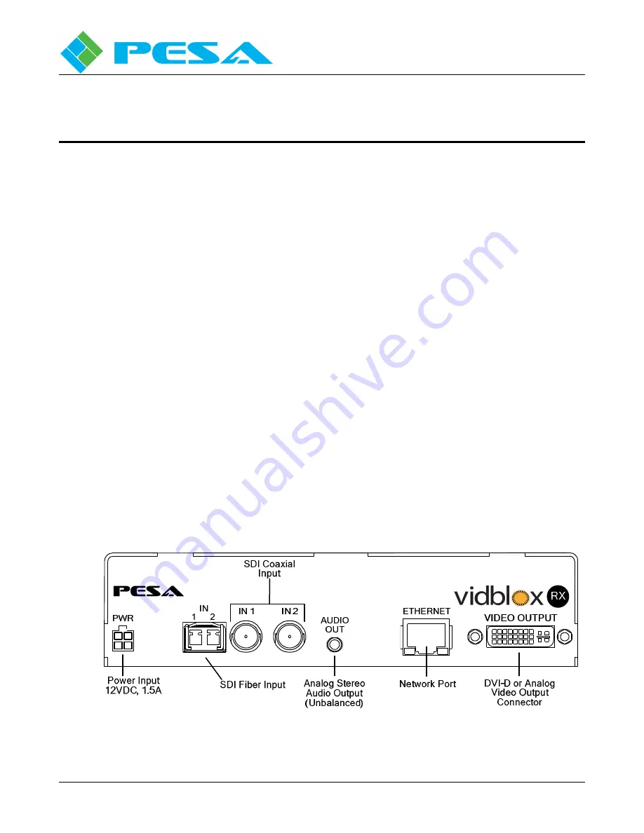
I/O connections and status LEDs for the 3G-SL RX module are shown by Figures 3-1 and 3-2, and
discussed in the following paragraphs. Differences between the 3G-SL and 3G-NE are noted in the text.
Using the illustrations for reference, complete connections to the module prior to applying power.
Figure 3-1 3G-SL RX Module Rear Panel I/O Connections
Summary of Contents for VIDBLOX 3G-NE RX
Page 57: ......


