V
IDBLOX
3G-SL
AND
3G-NE
RX
M
ODULE
Publication 81-9059-0667-0, Rev. C
March 2011
Proprietary Information of PESA
3-5
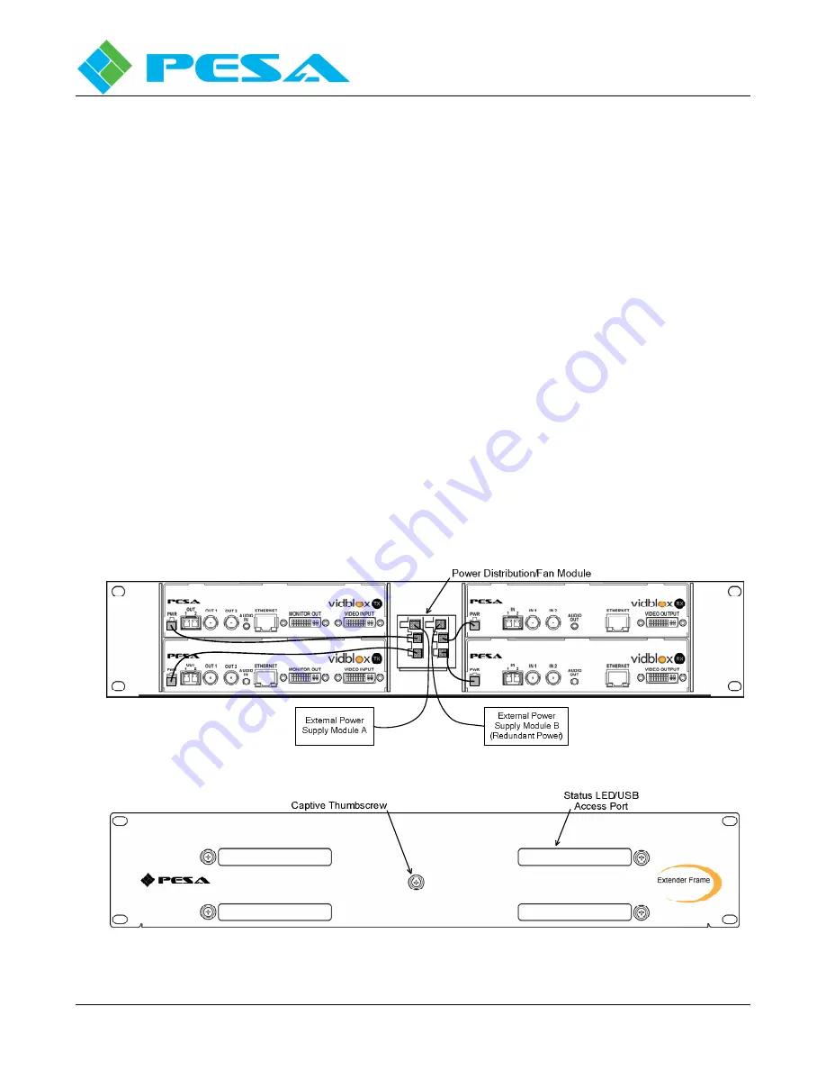
As shown in Figures 3-3 and 3-4, Vidblox modules are installed from the rear of the chassis and secured
using the captive thumbscrew on the front of the chassis. When a Vidblox module is installed in either
slot of the 1RU frame, the front panel LEDs and USB connector are accessible through the bottom
opening of the slot. It is easier, though certainly not a requirement, to install modules into the extender
frame chassis before mounting the frame in the equipment rack. Install modules as follows:
•
Slide each Vidblox module into the desired mounting slot of the extender frame as shown in
Figure 3-3.
•
Install the power distribution module into the center slot of the frame.
•
Secure all modules by tightening the captive thumb screw on the front of the frame as shown in
Figure 3-4.
•
Install a power jumper between any of the four power output connectors and the input power
connector on each Vidblox module as shown in Figures 3-3 and 3-5.
•
Mount the extender frame in an equipment rack at this time, if you chose to install the modules
with the extender frame out of the rack.
•
Ensure at least 50% of the open air space on either side of the extender frame is free of cables or
any other obstructions that may restrict air flow.
•
Connect the power output lead from the external 12VDC power supply to either of the main
power input connectors on the distribution module as shown in Figure 3-5.
•
If using a second, redundant, external power supply connect the lead from the redundant supply
to the unused power input connector.
•
Do not connect the external power supply(s) to a source of primary power until connections to
the Vidblox modules are completed as directed in Paragraph 3.2.
Figure 3-3 Extender Frame Rear View
Figure 3-4 Extender Frame Front View
Summary of Contents for VIDBLOX 3G-NE RX
Page 57: ......


