background image


Rev 02, 09/21 

Perma Pure LLC 

• A Halma Company • [email protected] • www.permapure.com


Telephone: 7

32-244-

0010 • Toll Free: 800

-337-

3762 • Fax: 

7

32-244-8140 

1

001 New Hampshire Ave., 

L

akewood, NJ 08701 USA 


6.3 

U

TILITY 

C

ONNECTIONS


6.3.1


Electrical Connections  

 
This model has no electrical power requirements. 

Grounding lug must be connected to earth ground to prevent electrostatic build up. 


6.3.2


Instrument Air Inlet 

 
The instrument air supply must be cleaned of particulates, liquids, and regulated to 60PSI-100PSI at the 
required flow rate. Perma Pure recommends both coalescing filtering and particulate filtering of the instrument 
air just before entry into the unit. Intrusion of particulates or liquid into the system will compromise 
performance.


6.3.3


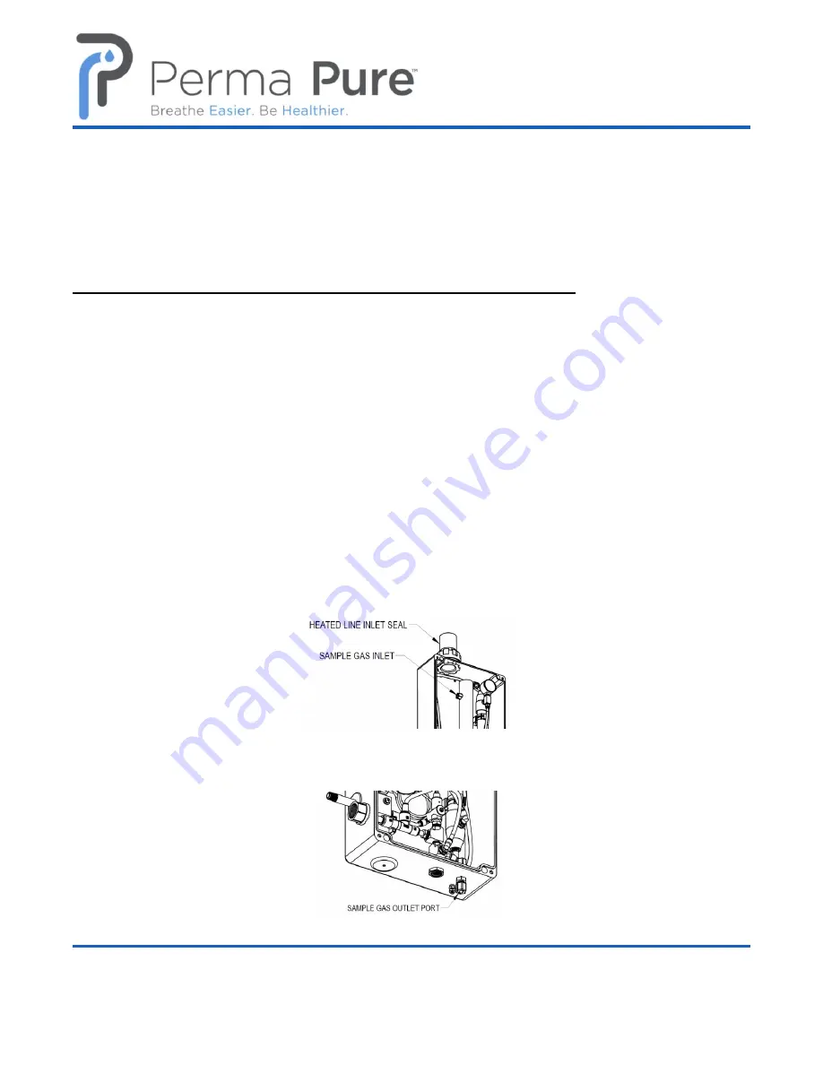
Heated Sample Gas Inlet and Dry Sample Gas Outlet 


Run the heated sample inlet line through the heat shrink entry seal and into enclosure. Connect the sample 
tubing to the compression fitting port, as indicated in the image below. Shrink entry seal tubing around the 
heated sample line with a heat gun to provide a water-tight seal.  


Connect the system to the sample gas analyzers or downstream sample pump via the port labeled 

“Sample 

Gas 

Outlet”.


Summary of Contents for Baldwin PCD-3000-DP

Page 1: ...elephone 732 244 0010 Toll Free 800 337 3762 Fax 732 244 8140 1001 New Hampshire Ave Lakewood NJ 08701 USA F Baldwin Hybrid Sample Gas Cooler PCD 3000 W PCD 3000 DP PCD 3000 PR PCD 3000 PR CD Sample Conditioning System Featuring Nafion Membrane Drying Technology User s Manual Rev 02 ...

Page 2: ...EM INSTALLATION 9 6 1 System Enclosure 9 6 2 Mounting 9 6 3 Utility Connections 10 6 3 1 Electrical Connections 10 6 3 2 Instrument Air Inlet 10 6 3 3 Heated Sample Gas Inlet and Dry Sample Gas Outlet 10 6 3 4 Filter Drain Outlet 11 6 3 5 Purge Air Exhaust Vent 12 6 3 6 Sample Gas Bypass Port 12 SYSTEM COMPONENTS 13 7 1 FUNCTION OF SAMPLE GAS FLOW COMPONENTS 13 7 1 1 Heat Exchanger 13 7 1 2 Sample...

Page 3: ...1 Flowmeter and Needle Valve 17 7 3 2 Vacuum Gauge 17 7 3 3 Purge Air Eductor 17 START UP PROCEDURE 17 8 1 Primary Sample Handling System Check Procedure 17 8 2 Hybrid Sample Gas Cooler System Check Procedure 17 8 2 1 Drain and purge exhaust lines 18 8 2 2 Instrument air source 18 8 2 3 Flowmeter and Needle valve 18 8 2 4 Vacuum gauge 18 8 2 5 Grounding Lug 19 SHUTDOWN PROCEDURE 19 DOS DON TS 19 M...

Page 4: ...D Sample Gas Dryer Disassembly 22 11 4 2 PD Sample Gas Dryer Assembly 22 REPLACEMENT PART LIST RECOMMENDED SPARES 22 12 1 Filter 23 12 2 Nafion Membrane PD Dryer 23 APPENDIX A DRAWINGS 24 13 1 System Interface PCD 3000 01 01 02 03 04 24 13 2 System Assembly PCD 3000 03 01 25 13 3 System Piping and Instrumentation Diagram PCD 3000 05 01 02 03 04 26 13 4 Q C Checkout list SE F 032 27 CONTACT US 28 ...

Page 5: ...m There may be local regulatory or government offices that can also help determine which codes and standards are necessary for safe installation and operation Equipment damage or serious personal injury can result from the failure to follow all applicable codes and standards We do not guarantee the products described in this publication are suitable for your particular application nor do we assume...

Page 6: ...environment around the equipment The gas stream exhaust must exit away from all personnel to prevent dangerous exposure NEVER operate the equipment with any part of the enclosure unsecured All operated doors and covers must be in place and secured prior to operation Electrical current may be present behind covers or doors even if tools are not necessary to access these components NEVER attempt ser...

Page 7: ...roduct shall in fact be suitable or desirable for any particular use or application 2 Buyer takes sole responsibility for the use and applications to which the product is put and Buyer shall conduct all testing and analysis necessary to validate the use and application to which Buyer puts the product for which Buyer may recommend the use or application of the product by others and 3 the characteri...

Page 8: ...ged Inspect outside packaging If there is any visible damage inform the carrier at the time of delivery This inspection is important Once the package is signed for responsibility for any visible damage then transfers to the consignee Unpack your equipment Visually inspect the outside of your equipment for any damage If there is any damage contact the carrier immediately Generally a carrier must be...

Page 9: ... designed to be wall mounted vertically with the inlet at the top It is suitable for outdoor installation If installed outdoors it is highly recommended to install it in a location that does not get direct sunlight or provide a method of shading the system In addition a method of protecting the system from direct rain is also highly recommended 6 2 MOUNTING Mount the system enclosure to a wall or ...

Page 10: ...I 100PSI at the required flow rate Perma Pure recommends both coalescing filtering and particulate filtering of the instrument air just before entry into the unit Intrusion of particulates or liquid into the system will compromise performance 6 3 3 Heated Sample Gas Inlet and Dry Sample Gas Outlet Run the heated sample inlet line through the heat shrink entry seal and into enclosure Connect the sa...

Page 11: ...ommended and the number of elbows should be kept to a minimum This port must be connected to an appropriate drain that can accept potentially acidic condensate and in the case of model PCD 3000 W a minimum of 0 25 scfm 7 lpm of air with entrained acidic mist See below for location of the drain port on the specific models WARNING Failure to properly connect this port may result in personal injury a...

Page 12: ...ce and or high sample gas flow restriction 6 3 6 Sample Gas Bypass Port This port is included on the PCD 3000 PR and PCD 3000 PR CD models and is capped at the factory It is typically used to decrease the system response time in applications where the sample gas is under pressure Use of this function is optional WARNING FAILURE TO PROPERLY VENT THE SYSTEM MAY RESULT IN PERSONAL INJURY AND OR PROPE...

Page 13: ... 1001 New Hampshire Ave Lakewood NJ 08701 USA SYSTEM COMPONENTS 7 1 FUNCTION OF SAMPLE GAS FLOW COMPONENTS 7 1 1 Heat Exchanger After condensate has been removed in the sample filter the heat exchanger utilizes heat from the incoming sample gas stream to slightly preheat the filtered sample gas just before it enters the PD dryer This keeps the ...

Page 14: ...he particulate matter is removed by collection on the filter element Any aerosol liquids are removed by first coalescing on the filter element and then collecting at the bottom of the filter bowl where the condensate can be removed by the drain system 7 1 4 Sample Gas Bypass Port Response time is the time it takes for the sample gas to travel from the sampling point to the analyzer In emission mon...

Page 15: ...ouched The driving force for the Nafion polymer to transfer water molecules is the difference in humidity levels water vapor pressure on either side of the membrane The Nafion polymer tries to attain equilibrium of the partial pressure of water vapor on either side of its membrane PD Series sample gas dryers consist of a bundle of 0 030 O D Nafion membrane tubing housed within a single large tube ...

Page 16: ...ed drain pump is intended to serve this purpose Collected liquids at the bottom of the filter bowl are pulled out of the filter by the pump via the bottom drain bulkhead fitting The pump outlet must be connected to an appropriate drain line as it will contain sample gas as well as potentially corrosive liquid 7 2 3 Model PCD 3000 PR This model includes a continuous drain for use with positive pres...

Page 17: ...mple and the purge The purge eductor generates vacuum which assists in generating this differential It operates on instrument air pressure The generated vacuum level and the resulting drying performance will be affected by fluctuations in supply pressure START UP PROCEDURE Read through this section completely before sample gas is allowed to flow through the system 8 1 Primary Sample Handling Syste...

Page 18: ...inlet to the system 8 2 3 Flowmeter and Needle valve Confirm the flow of purge gas flow through the PD sample dryer is 5 SLPM This must be verified with the vacuum line disconnected from the eductor See figure below This can be done by pushing the release ring on the push in tube fitting towards the body of the fitting and then pulling the tube out When re installing be sure the tube is completely...

Page 19: ...e the system in an ungrounded condition ground lug not connected DO visually inspect the condition of sample filters and any customer installed filters regularly DO regularly check the PD dryer purge vacuum and flow settings DO contact a Perma Pure representative with any question you may have about the operation of the system MAINTENANCE AND REPAIR 11 1 OPERATIONAL ADJUSTMENTS If at any time the ...

Page 20: ... cap while being sure the element is properly aligned with the protrusion on the top cap that keeps the element centered A slight twisting motion will help the o ring seat properly 9 Inspect the assembly for properly sealed o rings They will appear as lines that are about 1mm wide inside the glass shell Check for gaps twists or inconsistencies of the seal line 10 Replace bolt through hole in botto...

Page 21: ... drain valve o Pour water directly into the drain valve housing The valve should open before the level gets to the top and then close before the housing is empty If the valve does not open with the line from the filter to the drain valve disconnected apply low pressure air to the drain port This may help dislodge the needle from the seat If not the valve may need to be replaced If the valve is stu...

Page 22: ...ment tubing 5 Repeat steps 2 4 on the other end 6 While avoiding excessive sideward force of the element on the shell tube carefully remove one o ring from tube header see Figure 7 Gently pull tube element from opposite end of dryer 11 4 2 PD Sample Gas Dryer Assembly Tools Needed Phillips head screwdriver 1 Install one o ring item 7 in groove in one tube Header 2 Slip opposite tube header through...

Page 23: ...732 244 8140 1001 New Hampshire Ave Lakewood NJ 08701 USA 12 1 FILTER 12 2 NAFION MEMBRANE PD DRYER ITEM NO QTY PART NO DESCRIPTION 1 1 FF 250 E 2 5G Fine Filter Coalescing Sample Gas 2 2 100503 O Ring Viton Size 030 3 1 100502 O Ring Viton Size 009 ITEM No QTY PART NO DESCRIPTION 1 1 PD AP8001 PD Sample Gas Dryer Assembly 20 inch ...

Page 24: ...com www permapure com Telephone 732 244 0010 Toll Free 800 337 3762 Fax 732 244 8140 1001 New Hampshire Ave Lakewood NJ 08701 USA APPENDIX A DRAWINGS 13 1 SYSTEM INTERFACE PCD 3000 01 01 02 03 04 The drawings are attached paperclipped to this Adobe Acrobat file ...

Page 25: ...info permapure com www permapure com Telephone 732 244 0010 Toll Free 800 337 3762 Fax 732 244 8140 1001 New Hampshire Ave Lakewood NJ 08701 USA 13 2 SYSTEM ASSEMBLY PCD 3000 03 01 The drawings are attached paperclipped to this Adobe Acrobat file ...

Page 26: ... www permapure com Telephone 732 244 0010 Toll Free 800 337 3762 Fax 732 244 8140 1001 New Hampshire Ave Lakewood NJ 08701 USA 13 3 SYSTEM PIPING AND INSTRUMENTATION DIAGRAM PCD 3000 05 01 02 03 04 The drawings are attached paperclipped to this Adobe Acrobat file ...

Page 27: ...y info permapure com www permapure com Telephone 732 244 0010 Toll Free 800 337 3762 Fax 732 244 8140 1001 New Hampshire Ave Lakewood NJ 08701 USA 13 4 Q C CHECKOUT LIST SE F 032 The document is attached paperclipped to this Adobe Acrobat file ...

Page 28: ...0 Toll Free 800 337 3762 Fax 732 244 8140 1001 New Hampshire Ave Lakewood NJ 08701 USA CONTACT US For further assistance please contact us at Perma Pure LLC Tel 732 244 0010 1001New Hampshire Ave Tel 800 337 3762 Toll Free USA Lakewood NJ 08701 Fax 732 244 8140 www permapure com Email info permapure com ...

Reviews: