


This document is printed from SPI². Not for RESALE
SEBU8311-02
67
Maintenance Section
Cooling System Coolant (ELC) - Change
Drain
Pressurized System: Hot coolant can cause seri-
ous burns. To open the cooling system
fi
ller cap,
stop the engine and wait until the cooling system
components are cool. Loosen the cooling system
pressure cap slowly in order to relieve the pres-
sure.
1.
Stop the engine and allow the engine to cool.
Loosen the cooling system
fi
ller cap slowly in
order to relieve any pressure. Remove the cooling
system
fi
ller cap.
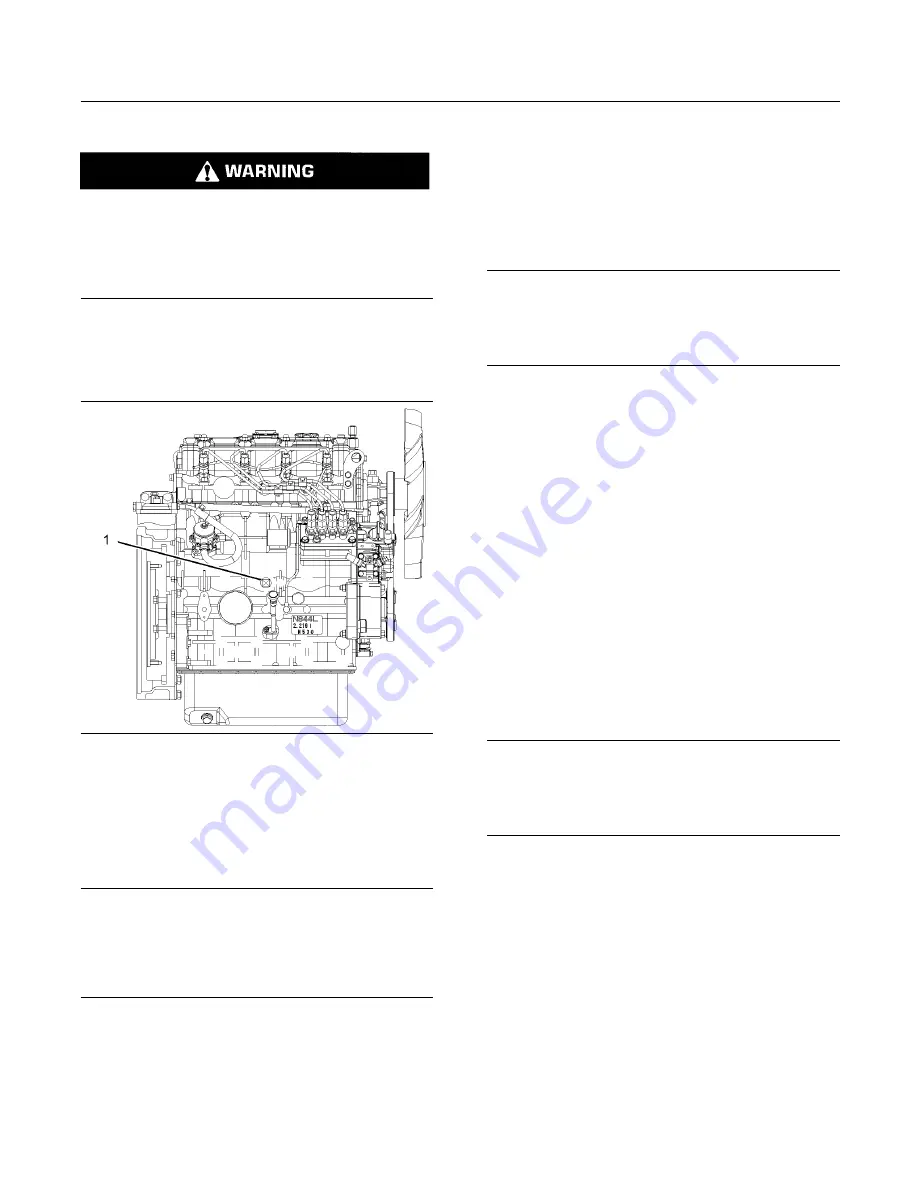
g01301065
Illustration 36
Typical example
2.
Open the drain cock or remove the drain plug (1)
on the engine. Open the drain cock or remove the
drain plug on the radiator.
Allow the coolant to drain.
NOTICE
Dispose of used engine coolant or recycle. Various
methods have been proposed to reclaim used coolant
for reuse in engine cooling systems. The full distillation
procedure is the only method acceptable by Perkins to
reclaim the coolant.
For information regarding the disposal and the
recycling of used coolant, consult your Perkins dealer
or your Perkins distributor.
Flush
1.
Flush the cooling system with clean water in order
to remove any debris.
2.
Close the drain cock or install the drain plug in the
engine. Close the drain cock or install the drain
plug on the radiator.
NOTICE
Do not
fi
ll the cooling system faster than 5 L
(1.3 US gal) per minute to avoid air locks.
Cooling system air locks may result in engine damage.
3.
Fill the cooling system with clean water. Install the
cooling system
fi
ller cap.
4.
Start and run the engine at low idle until the
temperature reaches 49 to 66 °C (120 to 150 °F).
5.
Stop the engine and allow the engine to cool.
Loosen the cooling system
fi
ller cap slowly in
order to relieve any pressure. Remove the cooling
system
fi
ller cap. Open the drain cock or remove
the drain plug on the engine. Open the drain cock
or remove the drain plug on the radiator. Allow
the water to drain. Flush the cooling system with
clean water.
Fill
1.
Close the drain cock or install the drain plug on the
engine. Close the drain cock or install the drain
plug on the radiator.
NOTICE
Do not
fi
ll the cooling system faster than 5 L
(1.3 US gal) per minute to avoid air locks.
Cooling system air locks may result in engine damage.
2.
Fill the cooling system with Extended Life
Coolant (ELC). Refer to the Operation and
Maintenance Manual, “Fluid Recommendations”
topic (Maintenance Section) for more information
on cooling system speci
fi
cations. Do not install the
cooling system
fi
ller cap.
3.
Start and run the engine at low idle. Increase the
engine rpm to high idle. Run the engine at high
idle for one minute in order to purge the air from
the cavities of the engine block. Stop the engine.
4.
Check the coolant level. Maintain the coolant level
within 13 mm (0.5 inch) below the bottom of the
pipe for
fi
lling. Maintain the coolant level in the
expansion bottle (if equipped) at the correct level.