background image

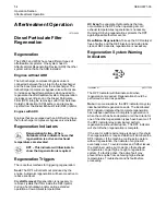
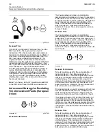
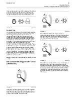
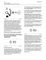
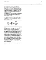
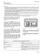
Illustration 42

g03679876

Once the amount of soot or sulfur collected has

reached, a critical threshold level the DPF indicator

and red STOP lamp will illuminate solid.
Regenerations may be locked out and require an
authorized Perkins distributor to perform
regeneration with service tool.

A fault code will be active for any DPF system-related
issue. Follow the troubleshooting guide to rectify the
issue.

If the DPF loses function, or is tampered with in any
way, the check engine lamp, and an amber action (if
equipped) will illuminate. A fault code will also
annunciate. The lamps and fault code will remain
active until the problem is rectified.

NOTICE

The engine and emissions control system shall be
operated, used, and maintained in accordance with
the instructions provided. Failure to follow the instruc-
tions could result in emissions performance that does
not meet the requirements applicable to the category
of the engine. No deliberate tampering with, or mis-
use of the engine emissions control system should
take place. Prompt action is critical to rectify any in-
correct operation, use, or maintenance of the emis-
sions control system.

Carbon Dioxide (CO

2

) Emissions

Statement

Emissions regulations require that the value of the
CO

2

emissions be reported to the end user. For this

engine, 717 g/kWh was determined to be the CO

2

value during the EU type approval process. This
value was recorded in EU type approval certificate.
This CO

2

measurement results from testing over a

fixed test cycle, under laboratory conditions, with a
parent engine representative of the engine family.
This value shall not imply or express any guarantee
of the performance of a particular engine.

i07489648

Selective


Catalytic


Reduction

Warning


System

The


selective


catalytic


reduction


(SCR)


system


is


a


system


used


to


reduce


NOx


emissions


from


the


engine.


Diesel


exhaust


fluid


(DEF)


is


pumped


from


the


DEF


tank


and


is


sprayed


into


the


exhaust


stream.


The


DEF


reacts


with


the


SCR


catalyst


to


reduce


NOx


and


leaves


a


nitrogen


and


water


vapor.


The


Exhaust


Gas


Recirculation


(EGR)


system


cools,


measures,


and


introduces


recalculated


exhaust


gas


into


the


intake


manifold


to


aid


in


NOx


reduction.

The


engine


and


emissions


control


system


shall


be


operated,


used,


and


maintained


in


accordance


with


the


instructions


provided


to


the


end


user


to


maintain


the


emissions


performance


of


the


engine


within


the


requirements


applicable


to


the


category


of


the


engine.


No


deliberate


tampering


with,


or


misuse


of


the


engine


emissions


control


system


should


take


place.


In


particular


regarding


deactivating,


or


not


maintaining


the


SCR


system.

SEBU9071-06

55

Operation Section

Selective Catalytic Reduction Warning System

Summary of Contents for 2206F-E13TA

Page 1: ...Operation and Maintenance Manual 2206F E13TA and 2206J E13TA Industrial Engine PP3 Engine PP4 Engine TGK Engine SEBU9071 06 en us December 2020 ...

Page 2: ...ormation that was available at the time that the publication was written The specifications torques pressures measurements adjustments illustrations and other items can change at any time These changes can affect the service that is given to the product Obtain the complete and most current information before you start any job Perkins dealers or Perkins distributors have the most current informatio...

Page 3: ...ics 18 Product Information Section General Information 19 Product Identification Information 26 Operation Section Lifting and Storage 29 Features and Controls 36 Engine Diagnostics 43 Engine Starting 48 Engine Operation 52 Aftertreatment Operation 54 Cold Weather Operation 62 Engine Stopping 64 Maintenance Section Refill Capacities 65 Maintenance Recommendations 83 Maintenance Interval Schedule 86...

Page 4: ...s manual Whenever a question arises regarding your engine or this manual please consult with your Perkins dealer or your Perkins distributor for the latest available information Safety This safety section lists basic safety precautions In addition this section identifies hazardous warning situations Read and understand the basic precautions listed in the safety section before operating or performi...

Page 5: ...r the engine as a convenient reminder Perkins also recommends that a maintenance record be maintained as part of the permanent record of the engine Your authorized Perkins dealer or your Perkins distributor can assist you in adjusting your maintenance schedule to meet the needs of your operating environment Overhaul Major engine overhaul details are not covered in the Operation and Maintenance Man...

Page 6: ...llustrations are not visible Use a cloth water and soap to clean the safety messages Do not use solvents gasoline or other harsh chemicals Solvents gasoline or harsh chemicals could loosen the adhesive that secures the safety messages The safety messages that are loosened could drop off the engine Replace any safety message that is damaged or missing If a safety message is attached to a part of th...

Page 7: ...292373 Universal Warning 1 Illustration 2 g01370904 One safety message is located on the left side of the engine One safety message is located on the right side of the engine SEBU9071 06 7 Safety Section Safety Messages ...

Page 8: ...a material safety data sheet MSDS for sulfuric acid Always follow the directions for first aid that are noted on a material safety data sheet MSDS for sulfuric acid i07676530 Additional Messages There are several specific messages on this engine The exact location of the messages and the description of the information are reviewed in this section Become familiar with all messages Make sure that al...

Page 9: ... that all protective guards and all covers are secured in place on the engine Never put maintenance fluids into glass containers Glass containers can break Use all cleaning solutions with care Report all necessary repairs Unless other instructions are provided perform the maintenance under the following conditions The engine is stopped Ensure that the engine cannot be started The protective locks ...

Page 10: ...tenance fluids into glass containers Glass containers can break Use all cleaning solutions with care Report all necessary repairs Unless other instructions are provided perform the maintenance under the following conditions The engine is stopped Ensure that the engine cannot be started Disconnect the batteries when maintenance is performed or when the electrical system is serviced Disconnect the b...

Page 11: ... grounded and bonded Consult with your fuel or fuel system supplier to ensure that the delivery system complies with fueling standards for proper grounding and bonding Avoid static electricity risk when fueling Ultra low sulfur diesel fuel ULSD fuel poses a greater static ignition hazard than earlier diesel formula tions with a higher sulfur contents Avoid death or serious injury from fire or expl...

Page 12: ...en you handle components that contain asbestos fibers Inhaling this dust can be hazardous to your health The components that may contain asbestos fibers are brake pads brake bands lining material clutch plates and some gaskets The asbestos that is used in these components is usually bound in a resin or sealed in some way Normal handling is not hazardous unless airborne dust that contains asbestos ...

Page 13: ...to touch with a bare hand Remove the filler cap slowly in order to relieve pressure Cooling system conditioner contains alkali Alkali can cause personal injury Do not allow alkali to contact the skin the eyes or the mouth Oils Skin may be irritated following repeated or prolonged exposure to mineral and synthetic base oils Refer to your suppliers Material Safety Data Sheets for detailed informatio...

Page 14: ...ily rags and any flammable materials in protective containers Do not smoke in areas that are used for storing flammable materials Do not expose the engine to any flame Exhaust shields if equipped protect hot exhaust components from oil or fuel spray in case of a line a tube or a seal failure Exhaust shields must be installed correctly Do not weld on lines or tanks that contain flammable fluids Do ...

Page 15: ...s Never check the battery charge by placing a metal object across the terminal posts Use a voltmeter or a hydrometer Incorrect jumper cable connections can cause an explosion that can result in injury Refer to the Operation Section of this manual for specific instructions Do not charge a frozen battery A frozen battery may cause an explosion The batteries must be kept clean The covers if equipped ...

Page 16: ...is i05768982 Mounting and Dismounting Do not climb on the engine or the engine aftertreatment system The engine and aftertreatment system have not been designed with mounting or dismounting locations Refer to the OEM for the location of foot and hand holds for your specific application i04257031 Before Starting Engine NOTICE For initial start up of a new or rebuilt engine and for start up of an en...

Page 17: ...utton if equipped ONLY in an emergency situation Do not use the Emergency Stop Button for normal engine stopping After an emergency stop DO NOTstart the engine until the problem that caused the emergency stop has been corrected Stop the engine if an overspeed condition occurs during the initial start up of a new engine or an engine that has been overhauled This may be accomplished by shutting off ...

Page 18: ...initiate an immediate action The following actions are available for engine monitoring control WARNING DERATE and SHUTDOWN These engine monitoring modes can limit engine speed and or the engine power Many of the parameters that are monitored by the ECM can be programmed for the engine monitoring functions The following parameters can be monitored as a part of the Engine Monitoring System Operating...

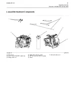
Page 19: ...ngine front lifting eye 2 Breather 3 Turbocharger elbow air out to air charge cooler 4 Valve mechanism cover 5 Engine rear lifting eye 6 NOx Reduction System NRS valve 7 Electronic control module 8 Starting motor 9 Air intake elbow from air charge cooler 10 Breather outlet pipe 11 Oil drain plug 12 Fuel transfer pump 13 Crankshaft vibration damper 14 Auto tensioner for drive belt 15 Idler roller f...

Page 20: ...r 25 Coolant intake 26 Oil filter 27 Oil drain valve 28 Twin secondary fuel filters 29 Flywheel housing 30 Flywheel 31 Oil sampling valve 32 Oil cooler 33 Exhaust manifold Note The secondary fuel filters 28 can be installed on either side of the engine Aftertreatment Systems The 2206F engine can be installed with different aftertreatment systems 20 SEBU9071 06 Product Information Section Model Vie...

Page 21: ... 15 g03809311 1 Clean emission module 2 Selective Catalytic Reduction SCR 3 Diesel Exhaust Fluid DEF injector 4 Mixer 5 Diesel Oxidation Catalyst DOC 6 Diesel Particulate Filter DPF 7 Exhaust intake 8 Exhaust outlet SEBU9071 06 21 Product Information Section Model View Illustrations ...

Page 22: ...ean Emission Module CEM 2 Exhaust outlet 3 Selective Catalytic Reduction SCR 4 DEF Injector 5 Diesel Particulate Filter DPF 6 CEM sensors and fuel system 7 Aftertreatment Regeneration Device ARD 8 Exhaust Inlet 22 SEBU9071 06 Product Information Section Model View Illustrations ...

Page 23: ...ift pump and primary fuel filter 3 NOx sensors 4 Flexible exhaust pipe 5 DEF Heated lines 6 ECM for aftertreatment 7 DEF tank header Pump Electronic Tank Unit PETU Some DEF tanks are combined with the pump electronics SEBU9071 06 23 Product Information Section Model View Illustrations ...

Page 24: ...atment regeneration device diesel oxidation catalyst the diesel particulate filter and the selective catalytic reduction The selective catalytic reduction requires the use of Diesel Exhaust Fluid DEF to be injected into the system to lower the emissions from the engine The DEF is stored and controlled by the pump electronic tank unit The DEF tank can be installed separate from the electronic pump ...

Page 25: ... use recommended fuels coolants and lubricants Use the Operation and Maintenance Manual as a guide for required engine maintenance Expected engine life is predicted by the average power that is demanded The average power that is demanded is based on fuel consumption of the engine over a time Reduced hours of operation at full throttle and or operating at reduced throttle settings result in a lower...

Page 26: ...mber engine model and arrangement number The engine information plate is located on top of the valve cover near the middle of the engine The following information is on the information plate engine serial number engine model engine arrangement number maximum altitude of the engine that is necessary to achieve the rated power horsepower high idle full load rpm fuel settings and other information Th...

Page 27: ...on may be needed by the Perkins distributor when inquiries are being made on the CEM Pump Electronic Tank Unit PETU and Pump Electronic Unit PEU Note Some applications may not have a diesel exhaust fluid tank installed into to the electronic unit Illustration 24 g03804717 Typical example 4 PETU Plate location Illustration 25 g03049116 Typical example PETU serial plate SEBU9071 06 27 Product Inform...

Page 28: ...ed to order parts Locate the information for your engine Record the information in the appropriate space Make a copy of this list for a record Keep the information for future reference Record for Reference Engine Model Engine Serial number Engine Low Idle rpm Engine Full Load rpm Primary Fuel Filter Secondary Fuel Filter Element Lubrication Oil Filter Element Auxiliary Oil Filter Element Total Lub...

Page 29: ... damage before performing any lifting Never bend the eyebolts and the brackets Never perform product lifting if components are damaged Read all the information within product lifting before any lifting is attempted Ensure that the correct set of lifting eyes for the assembly to be lifted have been selected Use a hoist to remove heavy components Use an adjustable lifting beam to lift the assembly A...

Page 30: ...tion 28 Install the load rings to position shown in illustration 26 and illustration 27 Tighten load ring bolts to a torque of 370 N m 272 lb ft 3 Use load rings and front engine lifting eye as the lift point for lifting the engine CEM and radiator 4 A suitable spreader bar must be used when lifting the engine CEM and radiator 5 Remove any ATAAC lines air cleaners or other attachments that would o...

Page 31: ...tachments Adjust the spreader bar and chains as necessary to maintain a lift within 5 degrees of horizontal in all directions The load ring part number is T401848 Engine Only Illustration 29 g03810206 1 Engine only lifting eyes SEBU9071 06 31 Operation Section Product Lifting ...

Page 32: ...6 Illustration 31 Typical example 1 PETU lifting eyes Product Storage Engine and Aftertreatment Your Perkins distributor can assist in preparing the engine for extended storage periods Some applications the engine can be equipped with delayed engine shutdown Allow at least 2 minutes after the engine has stopped before you turn the battery disconnect switch to OFF Disconnecting the battery power to...

Page 33: ...k and install the cap Seal all openings to the tank in order to prevent evaporation of the fuel and as a preservative 9 Remove the fuel injectors Apply 30 mL 1 oz of the mixture of oils 50 percent VCI oil and 50 percent engine oil into each cylinder Use a bar or a turning tool in order to turn over the engine slowly This procedure puts the oil on the cylinder walls Install all fuel injectors and t...

Page 34: ... procedure 4 Replace the fuel filter elements 5 Remove the plastic covers from the air cleaner elements 6 Use a bar or a turning tool in order to turn the engine in the normal direction of rotation The procedure ensures that no hydraulic locks or resistance exist 7 Before starting the engine remove the valve cover or covers Put a large amount of engine oil on the camshaft cam followers and valve m...

Page 35: ... the tank must be tested with a refractometer The DEF in the tank must meet the requirements defined in ISO 22241 1 and comply with table 2 1 If necessary drain the tank and fill with DEF that meet ISO 22241 1 2 Replace the DEF filter refer to this Operation and Maintenance Manual Diesel Exhaust Fluid Filter Clean Replace 3 Ensure that the drive belt is correctly installed Ensure that all engine c...

Page 36: ...urn the engine start switch to the OFF position Turn the battery disconnect switch to the OFF position and remove the key when you service the electrical system or any other engine components Turn the battery disconnect switch to the OFF position and remove the disconnect switch key after you operate the engine This will prevent the battery from being discharged The following problems can cause ba...

Page 37: ...he Industrial engine Specific engines may appear different due to the application Also illustration of the aftertreatment system may appear different due to the application Engine Views Illustration 34 g03821528 1 Camshaft timing sensor 2 Temperature sensor air charge cooler outlet 3 Inlet manifold pressure sensor 4 Barometric pressure sensor 5 Differential pressure sensor NOx Reduction System NRS...

Page 38: ...0 11 Coolant temperature sensor 12 Alternator 13 Crankshaft timing sensor 14 Fuel pressure sensor 15 Electric priming transfer pump 16 Fuel temperature sensor 38 SEBU9071 06 Operation Section Sensors and Electrical Components ...

Page 39: ...st Filter DPF outlet pressure sensor 2 DPF inlet pressure sensor 3 Diesel oxidation catalyst temperature sensor 4 Aftertreatment identification module 5 Temperature sensor probes 6 Diesel exhaust fluid injector SEBU9071 06 39 Operation Section Sensors and Electrical Components ...

Page 40: ...e Filter DPF Differential pressure sensor 5 DPF pressure sensor 6 Temperature sender 7 40 Pin connector 8 Selective Catalytic Reduction SCR temperature sensor 9 Fuel pilot pressure sensor 10 Fuel main pressure sensor 11 Identification Module 12 Temperature sender for Aftertreatment Regeneration Device ARD 40 SEBU9071 06 Operation Section Sensors and Electrical Components ...

Page 41: ...21970 1 NOx sensors 2 Diesel Exhaust Fluid DEF heated lines 3 Dosing control unit 4 Voltage load protection module 5 DEF Tank heater and DEF level gauge 6 Relays 7 Coolant diverter valve SEBU9071 06 41 Operation Section Sensors and Electrical Components ...

Page 42: ...37439 Typical example 1 DEF Level Sensor and DEF Temperature Sensor 2 Coolant Diverter Valve 3 Customer Connections 4 Dosing Control Module 5 Relays 6 Voltage Limiting Protection Module 42 SEBU9071 06 Operation Section Sensors and Electrical Components ...

Page 43: ...c code the code will be logged in the memory of the ECM The codes that have been logged by the ECM can be identified by the electronic service tool The active codes that have been logged will be cleared when the fault has been rectified or the fault is no longer active The following logged faults cannot be cleared from the memory of the ECM without using a factory password Overspeed low engine oil...

Page 44: ...d for future reference For more information on diagnostic codes refer to the Troubleshooting Guide for this engine i06193980 Configuration Parameters The engine electronic control module ECM has two types of configuration parameters The system configuration parameters and the customer specified parameters The electronic service tool is required in order to alter the configuration parameters System...

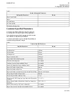
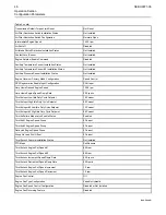
Page 45: ... Engine Speed Decelerating Ramp Rate 2000rpm s Ether Start Aid Configuration Not Installed Crankcase Pressure Sensor Installation Status Not Installed Ambient Air Temperature Sensor Installation Status Not Installed Engine Idle Shutdown Enable Status Disabled Engine Idle Shutdown Delay Time 5 0 min Engine Idle Shutdown Ambient Temperature Override Enable Status Disabled or Not Installed Delayed En...

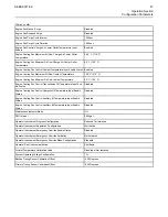
Page 46: ...cle Setpoint 10 Percent Throttle Input High Idle Duty Cycle Setpoint 90 Percent Throttle Input 2 Low Idle Duty Cycle Setpoint 10 Percent Throttle Input 2 High Idle Duty Cycle Setpoint 90 Percent Throttle Failure Mode Latch Enable Status Enabled Throttle 1 Engine Speed Droop 5 Percent Throttle 2 Engine Speed Droop 5 Percent Data Link Engine Speed Droop 5 Percent Droop No Load Fuel Offset 0 Percent ...

Page 47: ...Cooling Fan Control Hydraulic Oil Temperature Input Enable Status Disabled Engine Cooling Fan Control Auxiliary 1 Temperature Input Enable Status Disabled Engine Cooling Fan Control Auxiliary 2 Temperature Input Enable Status Disabled Maintenance Indicator Mode Off PM1 Interval 2500 gal Operator Inducement Progress Configuration Reduced Performance Operator Inducement Regulation Configuration Worl...

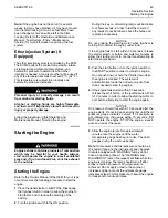
Page 48: ...haust to the outside Do not start the engine or move any of the controls if there is a DO NOT OPERATE warning tag or similar warning tag attached to the start switch or to the controls Ensure that the areas around the rotating parts are clear All of the guards must be put in place Check for damaged guards or for missing guards Repair any damaged guards Replace damaged guards and or missing guards ...

Page 49: ... test the circuits If any lamps do not illuminate check the bulbs and replace as necessary NOTICE Do not engage the starting motor when flywheel is turning Do not start the engine under load If the engine fails to start within 30 seconds release the starter switch or button and wait two minutes to allow the starting motor to cool before attempting to start the engine again 3 Push the start button ...

Page 50: ...ire is secure 3 Start the engine If the engine does not start check for a diagnostic code and consult your Perkins distributor i08134367 Starting with Jump Start Cables Do Not Use This Procedure in Hazardous Locations that have Explosive Atmospheres The connection of battery cables to a battery and the disconnection of battery cables from a battery may cause an explosion which may result in in jur...

Page 51: ...le to recharge fully batteries that are severely discharged The batteries must be replaced or charged to the proper voltage with a battery charger after the engine is stopped Many batteries which are considered unusable are still rechargeable Refer to Operation and Maintenance Manual Battery Replace and Testing and Adjusting Manual Battery Test i05359363 After Starting Engine Note In temperatures ...

Page 52: ...efore the gasses pass through the SCR Diesel Exhaust Fluid DEF is injected into the gas stream The DEF is controlled by the Pump Electronic Unit PEU The mixtures of DEF and the exhaust gas pass through the SCR reducing the NOx in the exhaust emissions The engine software will control the amount of DEF that will be required in order to keep the exhaust emission compliant This design of DPF will req...

Page 53: ...ep the air cleaner elements clean Ensure that the turbocharger is operating correctly For more information refer to this Operation and Maintenance Manual Turbocharger Inspect Maintain a good electrical system One faulty battery cell will overwork the alternator This fault will consume excess power and excess fuel The belt should be in good condition Refer to the Systems Operation Testing and Adjus...

Page 54: ... or during extended operation at low ambient temperatures HC Evap To evaporate Hydrocarbons that can accumulate in the DPF when operating at cold exhaust temperatures regeneration is necessary Running HC Evap regenerations protects the DPF against possible thermal events Desulfation Regeneration To keep the SCR catalyst free of sulfur and the DEF injector and mixing tube clean of DEF deposits rege...

Page 55: ...CO2 emissions be reported to the end user For this engine 717 g kWh was determined to be the CO2 value during the EU type approval process This value was recorded in EU type approval certificate This CO2 measurement results from testing over a fixed test cycle under laboratory conditions with a parent engine representative of the engine family This value shall not imply or express any guarantee of...

Page 56: ...level of inducement There are three inducement categories two for European Union that will trigger an escalating time inducement fault code Note The associated codes for each of the escalating time categories can be found in the Troubleshooting Guide under SCR Warning System Problem First occurrence When an escalating time inducement fault code becomes active for the first time Repeat occurrence W...

Page 57: ...nce and the DEF level is below 1 the engine will be in level 2 inducement The check engine lamp and emissions malfunction indicator lamp will illuminate and flash slowly The DEF level gauge amber lamp will remain lit The engine will have a 50 derate When the DEF tank has been emptied of all DEF the engine will have a 100 derate and be limited to 1000 rpm or low idle whichever is greater No further...

Page 58: ...lt There are two inducement categories If the inducement is a result of a category 1 fault then a level 1 inducement will occur for a duration of 18 hours If the inducement is a result of a category 2 fault then a level 1 inducement will occur for a duration of 5 hours There is no repeat occurrence for level 1 faults Illustration 49 g03676138 Reduced Performance If a fault condition exists for the...

Page 59: ...o Shutdown the engine may be restarted but will only run for 5 minutes at derated condition before shutting down again This action will continue until the issue is resolved Note Contact your Perkins dealer for repairs if a fault occurs Inducement Strategy for DEF Level Worldwide Illustration 51 g03676164 If the DEF level falls below 20 an amber indicator will illuminate next to the DEF level gauge...

Page 60: ...ucement faults Reduced Time The check engine and emissions malfunction indicator lamp will illuminate for a level 1 inducement related fault There are three inducement categories If the inducement is a result of a category 1 fault then a level 1 inducement will occur for a duration of 2 5 hours for first occurrence For repeat occurrence a category 1 level 1 inducement fault will occur for a durati...

Page 61: ...r the entire duration of inducement level 2 the strategy advances to inducement level 3 Inducement level 3 has the same actions for all categories The check engine lamp and the emissions malfunction indicator lamp will flash at a fast rate A red stop lamp will illuminate solid The engine will have a 100 derate and be limited to 1000 rpm or low idle whichever is greater If the final inducement acti...

Page 62: ...eration Following properties are used to define fuels low temperature capability Cloud point Pour point Cold Filter Plugging Point CFPP The cloud point of the fuel is the temperature at which waxes naturally found in the diesel fuel begin to form crystals The cloud point of the fuel must be below lowest ambient temperature to prevent filters from plugging Pour point is the last temperature before ...

Page 63: ...uel filter Select a fuel heater that is mechanically simple yet adequate for the application The fuel heater should also help to prevent overheating of the fuel High fuel temperatures reduce engine performance and the availability of engine power Choose a fuel heater with a large heating surface The fuel heater should be practical in size Small heaters can be too hot due to the limited surface are...

Page 64: ...have different control systems Ensure that the shutoff procedures are understood Use the following general guidelines in order to stop the engine 1 Remove the load from the engine so that the engine has no more than 30 power 2 Run the engine at the programmed low idle speed for at least 3 minutes 3 After the cool down period turn the start switch to the OFF position i01465494 After Stopping Engine...

Page 65: ...rankcase or sump plus standard oil filters Auxiliary oil filter systems will require additional oil Refer to the OEM specifications for the capacity of the auxiliary oil filter Coolant Refill Capacity To maintain the cooling system the total cooling system capacity must be known The capacity of the total cooling system will vary The capacity will depend on the size of the radiator capacity Table 6...

Page 66: ... to date recommendations Diesel Fuel Requirements Perkins is not in a position to continuously evaluate and monitor all worldwide distillate diesel fuel specifications that are published by governments and technological societies The Perkins Specification for Distillate Diesel Fuel provides a known reliable baseline to judge the expected performance of distillate diesel fuels that are derived from...

Page 67: ...6468 No equivalent test Pour Point C 6 C 42 8 F minimum be low ambient temperature D97 ISO 3016 Sulfur 3 mass 0 0015 maximum D5453 ISO 20846 Kinematic Viscosity 4 MM2 S cSt The viscosity of the fuel that is delivered to the fuel injec tion pump 1 4 minimum and 4 5 maximum D445 ISO 3405 Water and sediment weight 0 05 maximum D1796 ISO 3734 Water weight 0 02 maximum D1744 No equivalent test Sediment...

Page 68: ...erator of the engine has the responsibility of using the fuel that is prescribed by the EPA and other appropriate regulatory agencies NOTICE Operating with fuels that do not meet the Perkins rec ommendations can cause the following effects Start ing difficulty reduced fuel filter service life poor combustion deposits in the fuel injectors signifi cantly reduce service life of the fuel system Also ...

Page 69: ...lubricant for the fuel system components Fuel must have sufficient viscosity to lubricate the fuel system in both extremely cold temperatures and extremely hot temperatures If the kinematic viscosity of the fuel is lower than 1 4 cSt at the fuel injection pump damage to the fuel injection pump can occur This damage can be excessive scuffing and seizure Low viscosity may lead to difficult hot resta...

Page 70: ...atty Acid Methyl Esters FAME Raw pressed vegetable oils are NOTacceptable for use as a fuel in any concentration in compression engines Without esterification these oils solidify in the crankcase and the fuel tank These fuels may not be compatible with many of the elastomers that are used in engines that are manufactured today In original forms these oils are not suitable for use as a fuel in comp...

Page 71: ...ve in cleaning and preventing the formation of deposits Perkins Diesel Fuel Conditioner helps to limit deposit issues by improving the stability of biodiesel and biodiesel blends For more information refer to Perkins Diesel Fuel Cleaner Biodiesel fuel contains metal contaminants sodium potassium calcium and or magnesium that form ash products upon combustion in the diesel engine The ash can have a...

Page 72: ...Maintenance Manual Fluid Recommendations Fuel for Cold Weather Operation The European standard EN590 contains climate dependant requirements and a range of options The options can be applied differently in each country There are five classes that are given to arctic climates and severe winter climates 0 1 2 3 and 4 Fuel that complies with EN590 CLASS 4 can be used at temperatures as low as 44 C 47...

Page 73: ...s or cold temperature gel is rapid filter plugging of bulk fuel filters or application fuel filters To reduce downtime due to contamination follow these fuel maintenance guidelines Use high quality fuels per recommended and required specifications Fill fuel tanks with fuels of ISO 18 16 13 cleanliness level or cleaner in particular for engines with common rail and unit injection systems When you r...

Page 74: ...n dry or operate at a low level can affect the engine operation Because of the corrosive nature of DEF the correct materials must be used when filling a DEF tank DEF Quality The quality of DEF can be measured by using a refractometer The DEF must comply with ISO standard 22241 1 with the urea solution of 32 5 percent Perkins offer a T400195 Refractometer for checking the concentration of the DEF C...

Page 75: ... coolant at the proper operating temperature Cooling system prob lems can develop without water temperature regulators Many engine failures are related to the cooling system The following problems are related to cooling system failures Overheating leakage of the water pump and plugged radiators or heat exchangers These failures can be avoided with correct cooling system maintenance Cooling system ...

Page 76: ...xceed 50 percent glycol because of the reduced heat transfer capability of propylene glycol Use ethyl ene glycol in conditions that require additional protec tion against boiling or freezing Table 12 Propylene Glycol Concentration Freeze Protection 50 Percent 29 C 20 F To check the concentration of glycol in the coolant measure the specific gravity of the coolant Note Some commercially available c...

Page 77: ...LC contains organic corrosion inhibitors and antifoam agents with low amounts of nitrite Perkins ELC has been formulated with the correct amount of these additives to provide superior corrosion protection for all metals in engine cooling systems ELC is available in a premixed cooling solution with distilled water ELC is a 1 1 mixture The Premixed ELC provides freeze protection to 36 C 33 F The Pre...

Page 78: ...he Perkins Premixed ELC Operate the engine Ensure that all coolant valves open then stop the engine When cool check the coolant level ELC Cooling System Contamination NOTICE Mixing ELC with other products reduces the effective ness of the ELC and shortens the ELC service life Failure to follow these recommendations can result in shortened cooling system component life ELC cooling systems can withs...

Page 79: ...s in Table 16 to determine the amount of SCA that is required if necessary Table 16 Equation For Adding The SCA To The Heavy Duty Coolant For Maintenance V 0 023 X V is the total volume of the cooling system X is the amount of SCA that is required Table 17 is an example for using the equation that is in Table 16 Table 17 Example Of The Equation For Adding The SCA To The Heavy Duty Coolant For Main...

Page 80: ...itable API classifications to meet the emissions requirements and performance of your engine Refer to 18 for the correct oil specification for your engine Consult your Perkins distributor for more information on these multi grade oils NOTICE Perkins require the use of the following specifica tion of engine oil Failure to use the appropriate specification of engine oil will reduce the life of your ...

Page 81: ...nt temperature Supplemental heat may be required for cold soaked starts that are above the minimum temperature that is stated depending on the parasitic load and other factors Cold soaked starts occur when the engine has not been operated for a period of time This interval will allow the oil to become more viscous due to cooler ambient temperatures Aftermarket Oil Additives Perkins does not recomm...

Page 82: ...he following tests The Wear Rate Analysis monitors the wear of the engines metals The amount of wear metal and type of wear metal that is in the oil is analyzed The increase in the rate of engine wear metal in the oil is as important as the quantity of engine wear metal in the oil Tests are conducted to detect contamination of the oil by water glycol or fuel The Oil Condition Analysis determines t...

Page 83: ...he lubricating system turn off the engine i07915408 Welding on Engines with Electronic Controls NOTICE Because the strength of the frame may decrease some manufacturers do not recommend welding onto a chassis frame or rail Consult the OEM of the equip ment or your Perkins dealer regarding welding on a chassis frame or rail Correct welding procedures are necessary to avoid damage to the engines ECM...

Page 84: ...omponents are used as a ground for the welder or electrical electronic components are located between the welder ground and the weld current flow from the welder could severely damage the component 6 Protect the wiring harness from welding debris and spatter 7 Use standard welding practices to weld the materials i07014325 Severe Service Application Severe service is the application of an engine th...

Page 85: ...uality of the air The engine may be exposed to extended operation in an environment that is dirty or dusty unless the equipment is cleaned regularly Mud dirt and dust can encase components Maintenance can be very difficult The buildup can contain corrosive chemicals Buildup Compounds elements corrosive chemicals and salt can damage some components Altitude Problems can arise when the engine is ope...

Page 86: ...e Valve Lash Check 108 Every 500 Service Hours Battery Electrolyte Level Check 91 Engine Oil and Filter Change 106 Hoses and Clamps Inspect Replace 114 Every 500 Service Hours or 1 Year Cooling System Supplemental Coolant Additive SCA Test Add 95 Fuel System Primary Filter Water Separator Element Replace 109 Fuel System Secondary Filter Replace 110 Grounding Stud Inspect Clean Tighten 114 Every 20...

Page 87: ...ry 6000 Service Hours or 3 Years Coolant Extender ELC Add 95 Every 10 000 Service Hours DEF Manifold Filters Emission Related Component Replace 97 Every 12 000 Service Hours or 6 Years Coolant ELC Change 93 Every 492 100 L 130 000 US gal of Fuel Overhaul Considerations 115 SEBU9071 06 87 Maintenance Section Maintenance Interval Schedule ...

Page 88: ...ide the ARD combustion head by running a T400005 Plug Bore Brush through the hole in the ARD combustion head This tool scrapes debris from the seat and from the threads Run the brush through the hole several times Note The spark plug may be damaged if the spark plug is dropped Do not install a spark plug that has been dropped or a spark plug that is damaged 5 Carefully clean the spark plug using a...

Page 89: ...ir compressor is exposed Consult your Perkins distributor for assistance i07297207 Air Shutoff Test To ensure that the air shutoff valve always shuts down when the engine ingests gaseous fumes perform the test below at each oil change A test failure can indicate wear in the block off plate to valve body interface and or the bearing system 1 Place engine at low idle speed Ensure all accessories tha...

Page 90: ...nal injury or death Ensure proper ventilation for batteries that are in an enclosure Follow the proper procedures in or der to help prevent electrical arcs and or sparks near batteries Do not smoke when batteries are serviced The battery cables or the batteries should not be removed with the battery cover in place The bat tery cover should be removed before any servic ing is attempted Removing the...

Page 91: ...ery Cable Disconnect The battery cables or the batteries should not be removed with the battery cover in place The bat tery cover should be removed before any servic ing is attempted Removing the battery cables or the batteries with the cover in place may cause a battery explosion resulting in personal injury 1 Turn the start switch to the OFF position Turn the ignition switch if equipped to the O...

Page 92: ...n the cooling system and flush the cooling system before the recommended maintenance interval if the following conditions exist The engine overheats frequently Foaming is observed The oil has entered the cooling system and the coolant is contaminated The fuel has entered the cooling system and the coolant is contaminated Note Inspect the water pump and the water temperature regulator after the coo...

Page 93: ...iller cap Inspect the gasket that is on the cooling system filler cap If the gasket that is on the cooling system filler cap is damaged discard the old filler cap and install a new filler cap If the gasket that is on the cooling system filler cap is not damaged perform a pressure test The correct pressure for the cooling system filler cap is stamped on the face of the cooling system filler cap If ...

Page 94: ... to drain Flush the cooling system with clean water Close the drain valve Fill NOTICE Fill the cooling system no faster than 19 L 5 US gal per minute to avoid air locks 1 Fill the cooling system with Extended Life Coolant ELC Refer to this Operation and Maintenance Manual Fluid Recommendations for more information on cooling system specifications Do not install the cooling system filler cap 2 Star...

Page 95: ...sure 2 Maintain the coolant level within 13 mm 0 5 inch of the bottom of the filler pipe If the engine is equipped with a sight glass maintain the coolant level to the proper level in the sight glass Illustration 69 g00103639 Typical filler cap gaskets 3 Clean the cooling system filler cap and check the condition of the filler cap gaskets Replace the cooling system filler cap if the filler cap gas...

Page 96: ...urately check the coolant level This will also help in avoiding the risk of introducing an air lock into the coolant system 1 Slowly loosen the cooling system filler cap in order to relieve the pressure Remove the cooling system filler cap Note Always discard drained fluids according to local regulations 2 If necessary drain some coolant from the cooling system into a suitable container in order t...

Page 97: ...k neck adapter 4 Press filter screen into neck adapter and ensure that tabs 2 are located correctly Install cap 1 i07495346 DEF Manifold Filters Emission Related Component Replace Emissions Related Component NOTICE Ensure that the engine is stopped before any servic ing or repair is performed Type 1 manifold 1 Remove the manifold refer to Disassembly and Assembly Manifold DEF Heater Remove and Ins...

Page 98: ... base 6 Ensure that the band clamp is aligned as shown in illustration 74 to the flat section on the filter base Tighten the band clamp to 4 5 0 7 N m 40 6 lb in 1 Ensure that the filter does not bunch when tightening the band clamp 7 Install the manifold refer to Disassembly and Assembly Manifold DEF Heater Remove and Install for the correct procedure Type 2 Manifold To remove the DEF manifold an...

Page 99: ...2 to a torque of 4 5 N m 40 lb in 9 Install the DEF tank header refer to Disassembly and Assembly Manifold DEF Heater Remove and Install i07495337 Diesel Exhaust Fluid Emission Related Component Fill Illustration 77 g03714036 Typical example Ensure that the correct specification Diesel Exhaust Fluid DEF is used Ensure the cleanliness of the DEF refer to this Operation and Maintenance Manual Fluid ...

Page 100: ... affect DEF refer to this Operation and Maintenance Manual Diesel Exhaust Fluid in cold Weather for more information 5 The opening on the DEF tank 2 is a special diameter Ensure that the correct nozzle is used when filling the DEF tank Note At key on the DEF level gauge will show the last known DEF level and will transition to the new DEF level value 6 Install the DEF cap Check visually the DEF ta...

Page 101: ...r Emission Related Component Replace Illustration 80 g03363165 Typical example shown 1 Remove the diesel exhaust fluid DEF line 1 from the injector 4 2 Remove the coolant lines 2 from the injector 3 Remove the electrical connector 3 from the injector 4 Remove the bolts from the injector and remove the injector 5 Replace gasket The steel side of the gasket should face towards diesel particulate fil...

Page 102: ...n the engine is cleaned Pressure washers and steam cleaners should not be directed at any electrical connectors or the junction of cables into the rear of the connectors Avoid electrical components such as the alternator the starter and the ECM Protect the fuel injection pump from fluids to wash the engine Ensure that care is taken that the safety labels emission label and all other information la...

Page 103: ...eplacement of the air filter elements 1 Clean the outer casing of the air cleaner before removing the end cover 3 Note Before removal check the orientation of the end cover 3 Some air cleaners the end cover must be installed in the correctly aligned position 2 Release the clips 4 and remove the end cover 3 from air cleaner body 1 3 Remove the primary air filter element 2 and remove the secondary a...

Page 104: ...e frequently in environments that are severely dusty Replace the service indicator annually regardless of the operating conditions Replace the service indicator when the engine is overhauled and whenever major engine components are replaced Note When a new service indicator is installed excessive force may crack the top of the service indicator Tighten the service indicator to a torque of 2 N m 18...

Page 105: ...e FULL mark on the oil level gauge dipstick An overfull crankcase can cause the crankshaft to dip into the oil This will reduce the power that is devel oped and also force air bubbles into the oil These bubbles foam can cause the following problems re duction of the oil s ability to lubricate reduction of oil pressure inadequate cooling oil blowing out of the crankcase breathers and excessive oil ...

Page 106: ...ked for the following the quality of the oil the existence of any coolant in the oil the existence of any ferrous metal particles in the oil and the existence of any nonferrous metal particles in the oil i07014448 Engine Oil and Filter Change Hot oil and hot components can cause personal injury Do not allow hot oil or hot components to contact the skin Oil and Filter Change Intervals The standard ...

Page 107: ...ters are manufactured to Perkins specifi cations Use of an oil filter that is not recommended by Perkins could result in severe damage to the en gine bearings and crankshaft As a result of the larg er waste particles from unfiltered oil entering the engine lubricating system Only use oil filters recom mended by Perkins 1 Remove the oil filter with a suitable tool Illustration 86 g03806896 2 Clean ...

Page 108: ...t is not necessary Note All engine ratings must have the engine valve lash performed at 2500 hours Ensure that the engine is stopped before measuring the valve lash To obtain an accurate measurement allow the valves to cool before this maintenance is performed During valve adjustment visibly inspect the valve train of wear or damage Refer to Systems Operation Testing and Adjusting Engine Valve Las...

Page 109: ...scheduled interval The primary filter water separator also provides filtration in order to help extend the life of the secondary fuel filter The element should be changed regularly If a vacuum gauge is installed the primary filter water separator should be changed at 50 to 70 kPa 15 to 20 inches Hg Illustration 88 g03860980 1 Close the main fuel supply valve 2 Place a suitable container below the ...

Page 110: ... entering the fuel system i06098561 Fuel System Secondary Filter Replace Fuel leaked or spilled onto hot surfaces or electri cal components can cause a fire To help prevent possible injury turn the start switch off when changing fuel filters or water separator elements Clean up fuel spills immediately NOTICE Do not allow dirt to enter the fuel system Thoroughly clean the area around a fuel system ...

Page 111: ...sting and repair of the product Be prepared to collect the fluid with suitable contain ers before opening any compartment or disassem bling any component containing fluids Dispose of all fluids according to local regulations and mandates Fuel Tank Fuel quality is critical to the performance and to the service life of the engine Water in the fuel can cause excessive wear to the fuel system Water ca...

Page 112: ...helps to ensure the quality of the fuel When possible water separators should be used i07495345 Fumes Disposal Filter Element Emission Related Component Replace If Equipped Hot oil and hot components can cause personal injury Do not allow hot oil or hot components to contact the skin NOTICE Ensure that the engine is stopped before any servic ing or repair is performed NOTICE Care must be taken to ...

Page 113: ... Install cap A hand pressure only Cap B Illustration 93 g03814824 1 Loosen clip 1 and remove hose 2 Loosen clip 3 and remove hose 4 Refer to illustration 91 2 Remove cap B from breather body 7 If necessary remove O ring seal 8 and discard 3 Remove filter element 6 from breather body and discard old filter element 4 If necessary install new O ring seal 8 5 Ensure correct orientation of new filter e...

Page 114: ...d Clamps Inspect Replace Contact with high pressure fuel may cause fluid penetration and burn hazards High pressure fuel spray may cause a fire hazard Failure to follow these inspection maintenance and service in structions may cause personal injury or death If you inspect the engine in operation always use the proper inspection procedure in order to avoid a fluid penetration hazard Refer to Opera...

Page 115: ...he cooling system filler cap if the seals are damaged Install the cooling system filler cap 10 Start the engine Inspect the cooling system for leaks Fuel System The fuel system is split into two different sections high pressure and low pressure Ensure that the fuel pressure has been purged before any parts are removed loosened or replaced Check that connections and hoses are secure check for leaks...

Page 116: ...ine Use a light bulb behind the core to inspect the core for cleanliness Repeat the cleaning if necessary Inspect the fins for damage Bent fins may be opened with a comb Inspect these items for good condition welds mounting brackets air lines connections clamps and seals Make repairs if necessary i02568202 Starting Motor Inspect Perkins recommends a scheduled inspection of the starting motor If th...

Page 117: ...If only one belt is replaced the belt will carry more load than the belts that are not replaced The older belts are stretched The additional load on the new belt could cause the belt to break Drain the water and the sediment from fuel tanks on a daily basis in order to ensure that only clean fuel enters the fuel system Inspect the wiring and the wiring harnesses for loose connections and for worn ...

Page 118: ...equipped so as to conform at the time of sale to all applicable regulations adopted by the California Air Resources Board ARB b Free from defects in materials and workmanship which cause the failure of an emission related component to be identical in all material respects to the component as described in the engine manufacturer s application for certification for the warranty period 3 New non road...

Page 119: ...ating cost Records should be kept for the following items Fuel Consumption A record of fuel consumption is essential in order to determine when the load sensitive components should be inspected or repaired Fuel consumption also determines overhaul intervals Service Hours A record of service hours is essential to determine when the speed sensitive components should be inspected or repaired Document...

Page 120: ...intenance Log Table 19 Engine Model Customer Identifier Serial Number Arrangement Number Service Hours Quantity Of Fuel Service Item Date Authorization 120 SEBU9071 06 Reference Information Section Maintenance Log ...

Page 121: ...evel of protection for your Perkins Engine Coverage can be extended to 2 years 1 000 hours right up to 10 year 40 000 You can buy an ESC at any time during standard warranty even the last day Each Perkins Distributor has highly trained and experienced Perkins Product Support Service Technicians The Support Service is equipped and available around the clock to get your engine running again with the...

Page 122: ...tem Supplemental Coolant Additive SCA Test Add 95 Add the SCA If Necessary 96 Test for SCA Concentration 95 Crushing Prevention and Cutting Prevention 16 D Decommissioning and Disposal 121 DEF Filler Screen Emission Related Component Clean 96 DEF Manifold Filters Emission Related Component Replace Emissions Related Component 97 Type 1 manifold 97 Type 2 Manifold 98 Diagnostic Lamp 43 Diesel Exhaus...

Page 123: ...racteristics 69 Diesel Fuel Requirements 66 General Information 66 Foreword 4 California Proposition 65 Warning 4 Literature Information 4 Maintenance 4 Maintenance Intervals 5 Operation 4 Overhaul 5 Safety 4 Fuel and the Effect from Cold Weather 62 Fuel Conservation Practices 53 Fuel Related Components in Cold Weather 62 Fuel Heaters 63 Fuel Tanks 62 Fuel System Prime 108 Fuel System Primary Filt...

Page 124: ...n Information 26 Product Information Section 19 Product Lifting 29 Clean Emission Module CEM Lifting 32 Engine Only 31 Engine Clean Emission Module CEM and Radiator Lifting 29 Radiator Only 32 Product Storage Engine and Aftertreatment 32 Condition for Storage 32 R Radiator Clean 116 Radiator Restrictions 62 Reference Information 28 Record for Reference 28 Reference Information Section 119 Referenc...

Page 125: ...es 50 Stopping the Engine 64 System Pressure Release 83 Coolant System 83 Engine Oil 83 Fuel System 83 T Table of Contents 3 W Walk Around Inspection 116 Inspect the Engine for Leaks and for Loose Connections 116 Warranty Information 118 Warranty Section 118 Welding on Engines with Electronic Controls 83 SEBU9071 06 125 Index Section ...

Page 126: ......

Page 127: ...Maintenance Manual Delivery Date Product Information Model Product Identification Number Engine Serial Number Transmission Serial Number Generator Serial Number Attachment Serial Numbers Attachment Information Customer Equipment Number Dealer Equipment Number Dealer Information Name Branch Address Dealer Contact Phone Number Hours Sales Parts Service ...

Page 128: ...SEBU9071 2020 Perkins Engines Company Limited All Rights Reserved 128 December 2020 ...

Reviews: