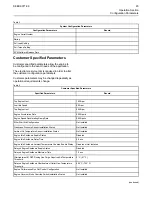
(Table 4, contd)
Engine Fan Manual Purge
Disabled
Engine Fan Suspend Purge
Disabled
Engine Fan Purge Cycle Interval
1200 sec
Engine Fan Purge Cycle Duration
180.0sec
Engine Fan Control Charge Air Cooler Outlet Temperature Input
Enable
Enabled
Engine Cooling Fan Maximum Air Flow Charge Air Cooler Outlet
Temperature
46.6° C (116° F)
Engine Cooling Fan Minimum Air Flow Charge Air Cooler Outlet
Temperature
40° C (104° F)
Engine Cooling Fan Control Coolant Temperature Input Enable Status Enabled
Engine Cooling Fan Maximum Air Flow Coolant Temperature
100° C (212° F)
Engine Cooling Fan Minimum Air Flow Coolant Temperature
90° C (194° F)
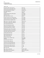
Engine Cooling Fan Control Transmission Oil Temperature Input Ena-
ble Status
Disabled
Engine Cooling Fan Control Hydraulic Oil Temperature Input Enable
Status
Disabled
Engine Cooling Fan Control Auxiliary #1 Temperature Input Enable
Status
Disabled
Engine Cooling Fan Control Auxiliary #2 Temperature Input Enable
Status
Disabled
Maintenance Indicator Mode
Off
PM1 Interval
2500 gal
Operator Inducement Progress Configuration
Reduced Performance
Operator Inducement Regulation Configuration
Worldwide
Operator Inducement Emergency Override Enable Status
Disabled
Operator Inducement Emergency Override Activation
Not Activated
Operator Inducement Emergency Override Mode Configuration
Standard
Operator Final Inducement Action
Shutdown
Air Inlet Temperature Calibration Value
Disabled or Not Installed
System Operating Voltage Configuration
12 V
Backup Timing Sensor Calibration Offset
-0.25 Degrees
Primary Timing Sensor Calibration Offset
-0.40 Degrees
SEBU9071-06
47

