


Illustration 89
g03806580
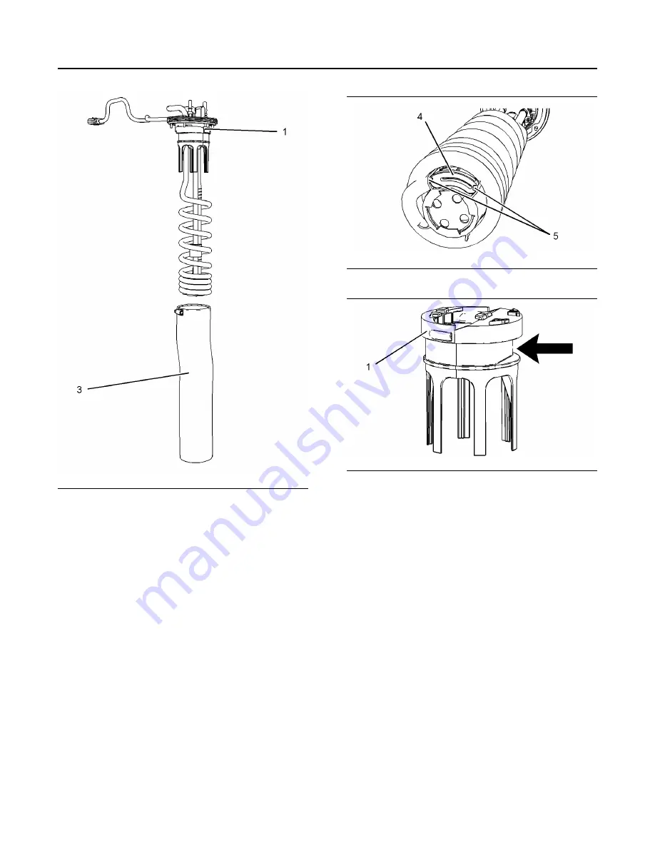
2.
Remove band clamp (2) from filter base (1).
3.
Remove filter (3) from filter base (1).
Illustration 90
g03806581
Illustration 91
g03806583
4.
Remove the suction filter (4) at the bottom of the
header coils by pulling tabs (5). Replace with a
new suction filter.
5.
Install new filter by pulling filter over the manifold
coils up to the bottom of the assembled filter base.
6.
Ensure that the band clamp is aligned, as shown in
illustration 91 , to the flat section on the filter base.
Tighten the band clamp to 4.5 ± 0.7 N·m
(40 ± 6 lb in) (1). Ensure that the filter does not
bunch when tightening the band clamp.
7.
Install the manifold, refer to Disassembly and
Assembly, “Manifold (DEF Heater) - Remove and
Install” for the correct procedure.
Type 2 Manifold
To remove the DEF manifold and the hoses
connections from the DEF tank, refer to Disassembly
and Assembly, Manifold (DEF Heater) - Remove and
Install.
104
M0087475-06
Maintenance Section
DEF Manifold Filters (Emission Related Component) - Replace