
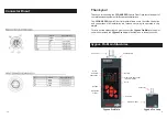

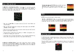


CURRENT & CONTINUOUS MODE:
Test display of the device with the
measurement configured in continuous mode (
CONT
) and real time (
CURR
). It
shows the current status of the copper lines, the attenuation of the fiber and the
number of errors detected until that moment.
?
When we press
ENTER
we reset the error counter both of fiber (
Fi.Err
) and
copper (
Cu.err
).
?
When we press the DOWN key we change the measurement from CURRENT
(
CURR
) to HISTORY (
HIST
).
?
If the tester does not detect any fault the counter is shown in green, otherwise the
number of errors will be shown in red.
?
The attenuation of the fiber is shown in green up to - 5.99 dB, in orange from - 6 to -
17.99 dB, and in flashing red over 18 dB.
?
A line failure occurs when a line that had been correct changes to malfunctioning
status with the exception of the initial status of the measurement display.
CURRENT & HISTORY MODE:
-
Test display
of the device with the measuring
configured in continuous mode (
CONT
) and history (
HIST
). It shows the cumulative
errors in the copper lines, the current status of the fiber and the number of fiber and
copper errors detected until that moment.
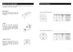
9
Configuration display
(
SETUP
) Allows to select the type of
measuring “MODE”, the status of the auto power-off
“SAVER” and the calibration of the device “CALIBRATE” (pic
4).
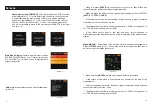
MODE:
You can select the type of measurement.
SINGLE
or
CONTINUOUS:
When se modify the type of measuring, the status on
the top of the screen is refreshed. The selected measuring type is reflected in the
indicators on the top of the screen. SINGLE ( Pic 5 ) and CONTINOUS ( Pic 6)
SAVER: Enables to configure the auto power-off of the device or the duration of the
stand-by status. Intervals of , 1 min, 5 min, 10, min,20 min, 30 min, 1 hour, 2 hours,
3 hours, and 4 hours (pic 7).
When the SAVER status is modified, the indicator on the top of the screen is
refreshed and changes to green if it is active of to red if the auto power-off is
activated.
6
Type of Measurement
Mode
Auto Power-off
Picture 4
Picture 5
Picture 6
Picture 7
Picture 10


