


5
Pantallas
-
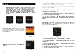
Home/start screen
(
POWER UP
). The tester model and SOFT version
are displayed ( pic 1.1). In this initial state, the device checks if there is
a head inserted in the main module. If there is no head a message
appears on the display( pic 1.2) If a correct head is detected it checks
whether the SFP model is correct; if it is not, a message is displayed
and it is not possible to move to the next status until the SFP is the right
one (pic 1.3)
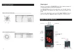
Main Menu Display.
Contain the main menu options
and the Cygnus Pro status. ( pic. 2 ) Option selection by
key up/down. The selected option is highlighted in
bright orange color.
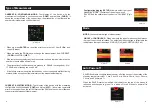
Help
explain the different options and functionalities
(picture 3)
?
When we press
ENTER
we reset both error counter of fiber(
Fi.Err
) and
cooper(
Cu.err
) as well as the status of the testing matrix.
?
When we press the DOWN key we change the measurement from HISTORY
(
HIST
) to CURRENT (
CURR
).
.
?
If the tester does not detect any fault the counter is shown in green, otherwise
the number of errors will be shown in red
?
The attenuation of the fiber is shown in green up to - 5.99 dB, in orange from - 6
to - 17.99 dB, and in flashing red over 18 dB.
?
A line failure occurs when a line that had been correct changes to
malfunctioning status with the exception of the initial status of the measurement
display.
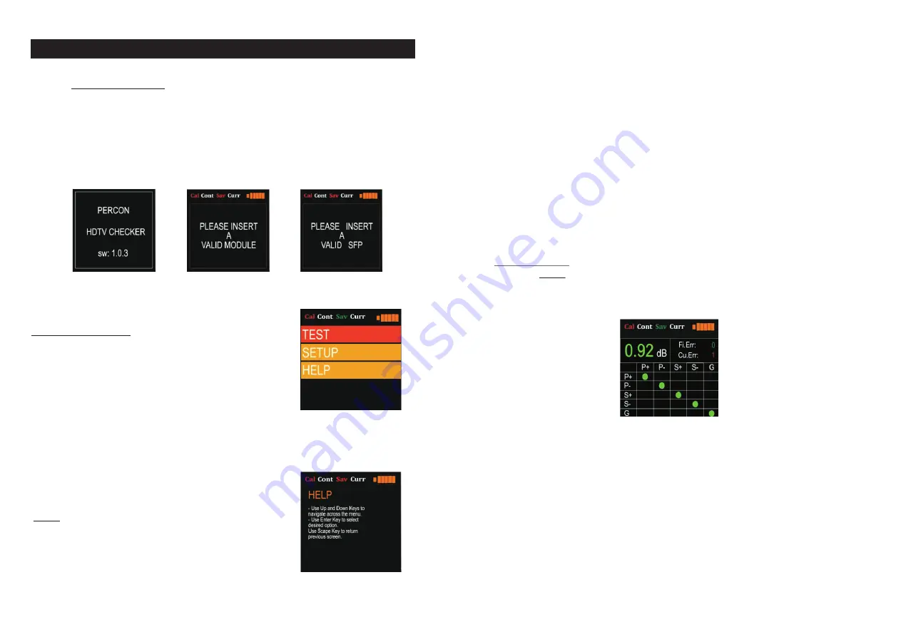
Modo SINGLE:
-
Test display of the device with the measurement configured in
SINGLE (
SING
) mode (pic 11). It shows the errors in the copper and fiber lines. If
an error occurs it increases the counter.
?
When we press
ENTER
we make a new measurement in this screen
?
A line failure occurs when a line presents any anomaly at the time of the
measurement.
?
If no error appears, the counter is shown in green, otherwise it would show the
number of errors in red (max 1 error)
?
The attenuation of the fiber is shown in green up to - 5.99 dB, in orange from - 6
to - 17.99 dB, and in flashing red over 18 dB.
10
Screens
Picture 1.1
Picture 2
Picture 3
Picture1.2
Picture 1.3
Picture 11


