background image

IUH-F117-V1-*

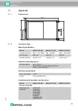
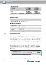
Appendix

 20

13

-0

4

47

A list of all available documents is displayed.

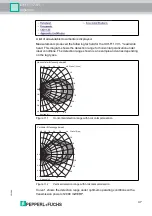
Measurements produced the following far field for the IUH-F117-V1-* read/write 

head. This diagram shows the detection range for horizontal polarization under 

ideal conditions. The detection range shown is an example and varies depending 

on the tag types.

Figure 11.1

Horizontal detection range with horizontal polarization

Figure 11.2

Vertical detection range with horizontal polarization

Curve 1 shows the detection range under optimum operating conditions with a 

transmission power of 2000 mW ERP.

Abstand [m]

Winkel [Grad]

Horizontaler Erfassungsbereich

5,0 6,0 


0,0

1,0

2,0

3,0

4,0

90 80  70  60 

50 

40

20

10

0

-10

-20

30

-30

1

2

3

Abstand [m]

Winkel [Grad]

Vertikaler Erfassungsbereich

5,0 6,0 


0,0

1,0

2,0

3,0

4,0

90 80  70  60 

50 

40

20

10

0

-10

-20

30

-30

1

2

3

Summary of Contents for IUH-F117-V1-CN

Page 1: ...IUH F117 V1 EU IUH F117 V1 US IUH F117 V1 CN Read Write Head for IDENTControl FACTORY AUTOMATION MANUAL...

Page 2: ...Terms of Delivery for Products and Services of the Electrical Industry published by the Central Association of the Electrical Industry Zentralverband Elektrotechnik und Elektroindustrie ZVEI e V in it...

Page 3: ...Code EPC 12 4 2 7 Influence of various materials on the sensing range 13 4 2 8 Dense Reader Mode DRM 13 4 2 9 Frequency Hopping Method 14 4 2 10 Relevant Standards for UHF 15 4 3 General Functions an...

Page 4: ...1 General 29 7 2 Basic Command Process 29 7 3 Command Overview 30 7 4 Read Write Commands 31 7 5 Configuration Commands 35 7 5 1 ChangeTag Command 35 7 5 2 Read and Write Parameters 37 7 5 3 Parameter...

Page 5: ...ntire range of device functions avoid faulty operation and the associated errors reduce costs from downtimes and incidental repairs increase the effectiveness and operating efficiency of your plant St...

Page 6: ...io frequency energy and if not installed and used in accordance with the instruction manual may cause harmful interference to radio communications Operation of this equipment in a residential area is...

Page 7: ...es not issue any licenses to its own or third party patents or other industrial property rights in this document Danger This symbol indicates an imminent danger Non observance will result in personal...

Page 8: ...pecialist The operating company bears responsibility for observing locally applicable safety regulations Store the not used device in the original packaging This offers the device optimal protection a...

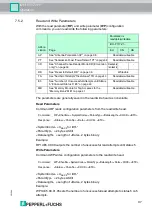
Page 9: ...ance with EN 302208 In the USA a maximum of 4 Weirp are allowed In China a maximum of 2 Werp are allowed 4 2 3 Permissible Frequency Range of UHF The frequency range for UHF in which the IUH F117 V1 r...

Page 10: ...able Tag Types UHF 868 MHz on page 36 column UII EPC Bank 10 Tag ID TID 4 bytes MDID TMN 0 4 or 8 bytes Bank 11 User memory Depending on the tag type see table Tag Types UHF 868 MHz on page 36 column...

Page 11: ...nly code ES and enhanced write special read only code EP see Single Read Special Read Only Code SS on page 31 see Single Write Special Read Only Code SP on page 32 see Enhanced Read Special Read Only...

Page 12: ...ust not contain any valid EPC codes The EPC numbers are managed and assigned by GS1 To obtain EPC numbers please contact the GS1 branch in your country http www gs1 com contact The electronic product...

Page 13: ...material The mounting surface often affects the read range much more than the material between the transponder and the read write head The graph shows the effect of different materials on the sensing...

Page 14: ...20 925 MHz are available for UHF RFID readers This read write head uses the 920 925 MHz range The range is split into 20 channels each with a bandwidth of 250 kHz On channels 0 1 18 and 19 only 100 mW...

Page 15: ...ure 4 4 4 2 10 Relevant Standards for UHF European radio standards EN 300220 and EN 302208 Usage recommendations for RFID type labels information about recycling installation of readers and antennae I...

Page 16: ...rotects against failures such as antenna short circuiting and electrostatic discharge 4 4 Indicators and Controls The IUH F117 V1 read write head has two dual LEDs green yellow The two LEDs are locate...

Page 17: ...ace Designation 4 read write heads Ethernet IC KP B17 AIDA1 2 read write heads PROFIBUS IC KP2 2HB6 V15B Ethernet IC KP2 2HB17 2V1D Serial IC KP2 2HRX 2V1 1 read write head PROFIBUS IC KP2 1HB6 V15B I...

Page 18: ...ht female angled male V1 G 2M PUR ABG V1 W 5 m long straight female angled male V1 G 5M PUR ABG V1 W 10 m long straight female angled male V1 G 10M PUR ABG V1 W 20 m long straight female angled male V...

Page 19: ...Installation accessories Two different mounting brackets are available to mount the read write head on a wall or pole Figure 4 9 IUZ MH10 Accessories Designation Length 2 m straight socket V1 G 2M PUR...

Page 20: ...e supplier Check the package contents against your purchase order and the shipping documents for Delivery quantity Device type and version in accordance with the type label Any accessories ordered Ret...

Page 21: ...ing the read write head please observe the minimum distances The lateral distance between the read write head and metals or liquids should be at least 50 cm The distance between the read write head an...

Page 22: ...order for a UHF system to utilize the full sensing range Refer to the corresponding data sheet for details on the polarization of the transponder Linear polarization the direction of the vector of an...

Page 23: ...lights up green on the device If the LED does not light up on the device the power supply is not connected correctly If the LED lights up red a device error has occurred If the PWR ERR LED flashes re...

Page 24: ...resistance and low inductance write head Control IDENTControl INTERBUS Note If cables with double shields are used e g wire mesh and metalized foil the both shields must be connected together with lo...

Page 25: ...ower ETX 1 byte 03hex read only code TID 4 bytes an optional 4 or 8 bytes Ldata Length of the data in bytes 2 bytes Use in multiframe protocol Length 1 character hexASCII number of data bytes Permitte...

Page 26: ...ntrol interface can be found in the manual SystemCode U for read write head IUH TagType 2 ASCII characters UII EPC Unique Item Identifier memory area of a tag in accordance with EPC Gen 2 ISO IEC 1800...

Page 27: ...measurement range see Single Write Special Read Only Code SP on page 32 Serial Ethernet PROFIBUS Command EF1 00 04 1D 03 1D 03 Confirmation 00 06 1D 03 FF 0B 1D 03 FF 0B Response 35 31 00 06 1D 03 05...

Page 28: ...to 1F4hex via the write parameter PT command Serial Ethernet PROFIBUS Command SS10 00 04 0A 02 0A 02 Confirmation 00 06 0A 02 FF 2F 0A 02 FF 2F Response 30 31 34 00 1 1 22 33 44 55 66 77 88 99 AA BB...

Page 29: ...so reflected off objects in the vicinity meaning that multiple partial waves overlap with the waves radiated by the read write head This overlap causes interference i e exaggeration and dampening of t...

Page 30: ...itable transmission frequency from the available frequencies and performs the specified number of attempts 7 3 Command Overview The commands in the list are described in detail on the following pages...

Page 31: ...s the measurement range a status 5 message is reported to the control interface Example EF1 continuously reads the read only code to IDENTControl channel 1 Single Read Special Read Only Code SS This c...

Page 32: ...gs according to EPC Gen 2 ISO IEC 18000 63 Length Length of the SpecialFixcode in ASCIIhex The data length Length must be a whole number multiple of 2 bytes because in accordance with EPC Gen 2 ISO IE...

Page 33: ...trol word Enhanced Write Special Read Only Code EP This command continuously attempts to write a Length byte long UII EPC code to tags according to EPC Gen 2 ISO IEC 18000 63 If the command was execut...

Page 34: ...ess 0001 Single Write Words SW One attempt is made to write WordNum 32 bit words from the address WordAddr Example SW1000101ABCD writes the 4 byte long word ABCD from memory address 0001 Note The memo...

Page 35: ...ells the R W system with which tag type to communicate Example CT180 sets the tag type for IDENTControl channel 1 to IUC80 CT180 sets a generally valid tag type which allows the read only code to be r...

Page 36: ...2 32 240 E2006003hex seq no Yes 64 73 EPC Class 1 Gen 2 Alien Higgs 2 IUC73 32 32 96 E2003411hex No 74 EPC Class 1 Gen 2 NXP UCode EPC G2 IUC74 32 32 96 E2006001hex seq no Yes 28 75 EPC Class 1 Gen 2...

Page 37: ...ample WP1UE5 00 01 05 sets the number of unsuccessful read attempts to status 5 on 5 attempts Abbre viation Page Parameter is readable writeable IUH F117 V1 EU CN US AP See Antenna Polarization AP on...

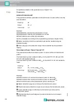
Page 38: ...the transmission power or reads out the set transmission power The transmission power is stated in mWerp for the IUH F117 V1 EU and IUH F117 V1 CN read write heads The transmission power is stated in...

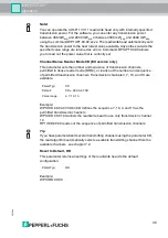
Page 39: ...ead to the default configuration Example WP1URD 00 00 Note You can operate the IUH F117 V1 read write head only with internally specified transmission power For the software you can enter any transmis...

Page 40: ...writing Increased response time Number of Unsuccessful Attempts until Status 5 Enhanced Status 5 E5 This parameter sets the number of unsuccessful read write attempts until a status 5 is output for a...

Page 41: ...Status Meaning 0 The command was executed correctly 1 Reserved 2 Switch on message reset was executed 3 Reserved 4 The command is incorrect or incomplete The parameter is not in the valid area 5 No re...

Page 42: ...IUH F117 V1 Service and Maintenance 8 Service and Maintenance The device is designed and constructed to function stable over long periods of time For this reason regular cleaning or maintenance is un...

Page 43: ...heads in the local vicinity Change the setting of the transmission channels Reduce the transmission power Status A message Check whether there are multiple tags in the measurement range Remove the ta...

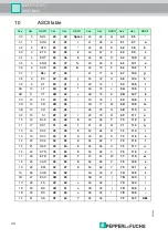
Page 44: ...75 K 6B 107 k 0C 12 FF 2C 44 4C 76 L 6C 108 l 0D 13 CR 2D 45 4D 77 M 6D 109 m 0E 14 SO 2E 46 4E 78 N 6E 110 n 0F 15 SI 2F 47 4F 79 O 6F 111 o 10 16 DLE 30 48 0 50 80 P 70 112 p 11 17 DC1 31 49 1 51 8...

Page 45: ...865 1 867 9 MHz 902 928 MHz 920 5 924 5 MHz Emitted power ERP 2 W EIRP 4 W ERP 2 W Operating distance maximum 6 m maximum 6 m maximum 6 m LED green yellow green power on green flashing read write atte...

Page 46: ...be tested for the intended application under real conditions Please note the distance tables The distance tables and additional information regarding your product can be found at http www pepperl fuch...

Page 47: ...g on the tag types Figure 11 1 Horizontal detection range with horizontal polarization Figure 11 2 Vertical detection range with horizontal polarization Curve 1 shows the detection range under optimum...

Page 48: ...anced read read only code EF command continuously attempts to read a read only code Time taken for the read only code to be successfully read 20 ms Distance from the tag to the read write head 1 5 m f...

Page 49: ...IUH F117 V1 Appendix 2013 04 49...

Page 50: ...GmbH 68307 Mannheim Germany Tel 49 621 776 0 E mail info de pepperl fuchs com USA Headquarters Pepperl Fuchs Inc Twinsburg Ohio 44087 USA Tel 1 330 4253555 E mail sales us pepperl fuchs com Asia Paci...

Reviews: